Thermal superconduction heat dissipation plate, thermal superconduction radiator and 5G base station equipment

A technology for base station equipment and radiator substrates, which is applied in the fields of thermal superconducting radiators, radiators, and 5G base station equipment. It can solve problems such as uneven heat dissipation, low heat dissipation efficiency, and bulkiness, and achieve high integration and temperature uniformity. , prolong the service life of the equipment and improve the performance of the equipment

Pending Publication Date: 2020-08-07
ZHEJIANG JIAXI TECH CO LTD
View PDF0 Cites 1 Cited by
  • Summary
  • Abstract
  • Description
  • Claims
  • Application Information

AI Technical Summary

Problems solved by technology

[0003] In view of the above-mentioned shortcomings of the prior art, the purpose of the present invention is to provide a thermal superconducting heat sink, radiator and 5G base station equipment, which are used to solve the problems of the all-aluminum sheet-slotted radiator or die-cast radiator in the prior art. It is large and bulky, and also has the disadvantages of uneven heat dissipation and low heat dissipation efficiency, which cannot meet the heat dissipation requirements of 5G communication base station equipment with high integration, high power, miniaturization, light weight, and high heat flux density

Method used


Image

  • Thermal superconduction heat dissipation plate, thermal superconduction radiator and 5G base station equipment
  • Thermal superconduction heat dissipation plate, thermal superconduction radiator and 5G base station equipment
  • Thermal superconduction heat dissipation plate, thermal superconduction radiator and 5G base station equipment

Examples


Embodiment 1

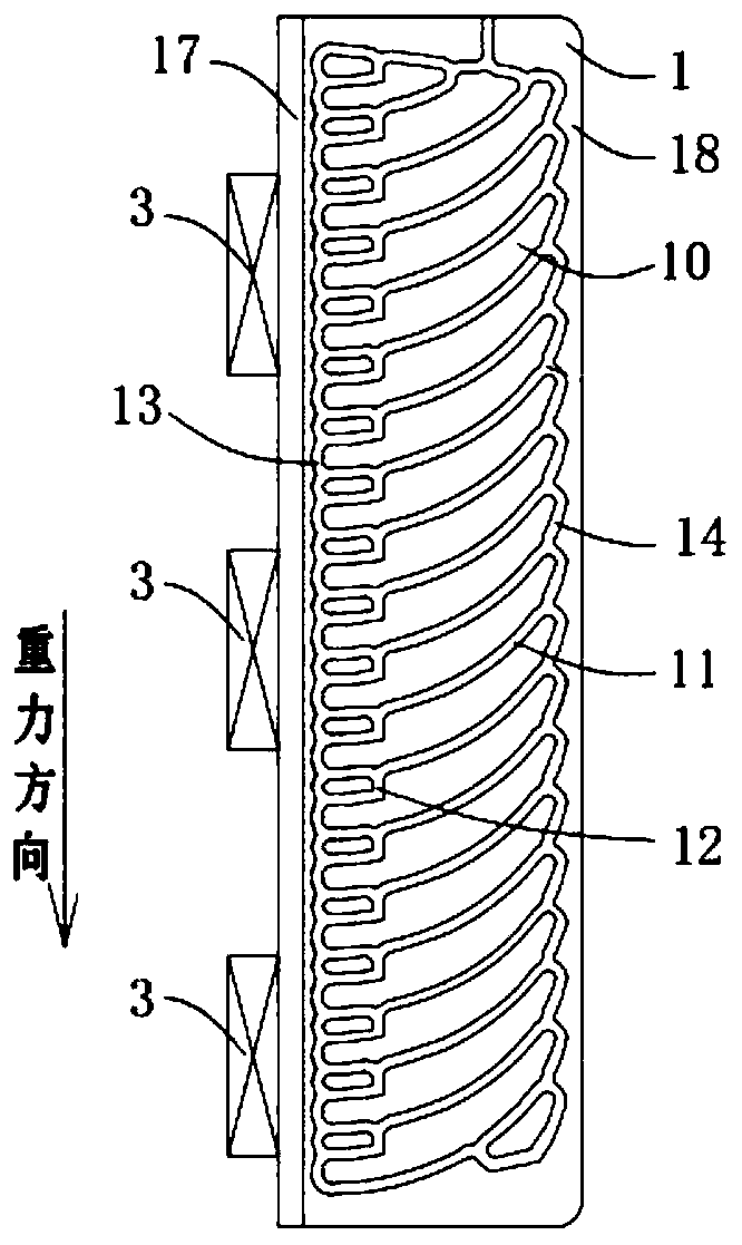
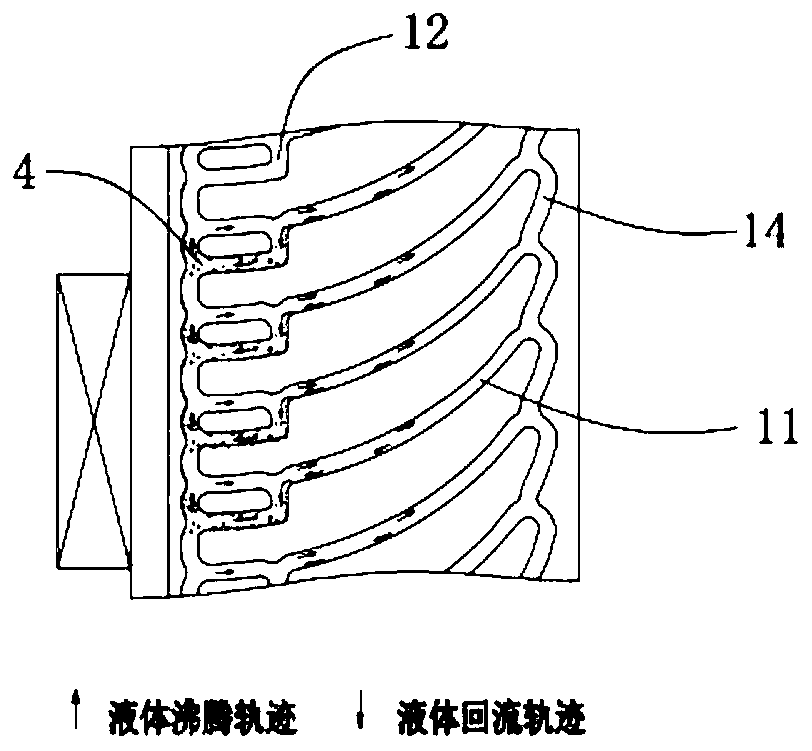
[0041] Such as Figure 1 to Figure 2 As shown, the present invention provides a thermal superconducting heat sink 1 in which a heat dissipation main pipe 11, a liquid drop pipe 12, a heat receiving side communication pipe 13 and a condensing side communication pipe 14 are distributed. The heat-receiving-side communication pipeline 13 is located on the side of the thermal superconducting heat sink 1 adjacent to the heating device 3, and the condensing-side pipeline is located on the opposite side of the heat-receiving-side communication pipeline 13; The heat dissipation main pipe 11 is connected between the heat receiving side communication pipe 13 and the condensing side communication pipe 14, and the liquid drop pipeline 12 is located under the heat dissipation main pipe 11 in a one-to-one correspondence with one end It is connected with the corresponding heat dissipation main pipe 11, and the other end is connected with the heat-receiving side communication pipe 13; the heat ...

Embodiment 2

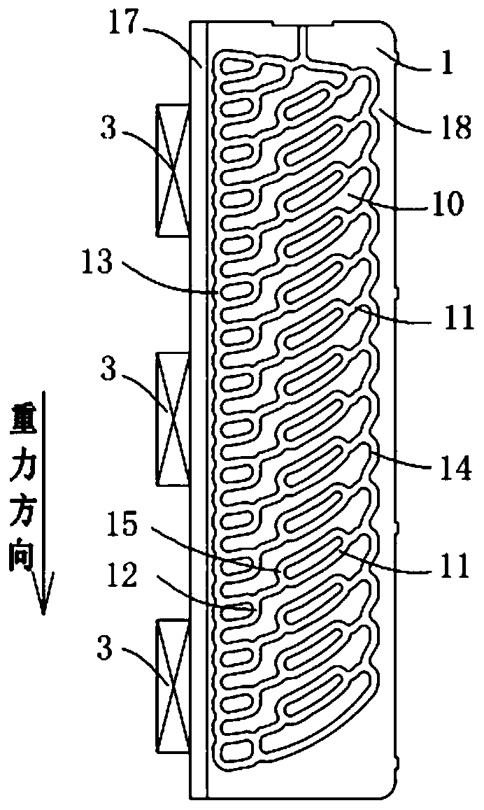
[0050] Such as image 3 with Figure 4 As shown, this embodiment provides a thermal superconducting heat sink 1 of another structure. The difference between the thermal superconducting heat sink 1 of this embodiment and the first embodiment is that the thermal superconducting heat sink 1 of this embodiment further includes a plurality of steam rising pipes 15 which are located at all locations one by one. Above the heat dissipation main pipe 11, and both ends are connected with the heat dissipation main pipe 11, and the steam rising pipe 15 and the liquid falling pipe 12 are usually spaced apart, and the projections of the two in the longitudinal direction do not overlap . The steam rising pipe 15 may include a straight section and a bent section at both ends of the straight section, so the steam rising pipe 15 and the heat dissipation main pipe 11 enclose a plurality of similar rectangular islands without pipes. Area 10, please refer to image 3 . The thermal superconducting...

Embodiment 3

[0052] Such as Figure 5 As shown, this embodiment provides a thermal superconducting heat sink 1 of another structure. The difference between the thermal superconducting heat sink 1 of this embodiment and the second embodiment is that both ends of the steam rising pipe 15 of the thermal superconducting heat sink 1 of the second embodiment are connected to the heat dissipation main pipe 11, and this embodiment In the example, although there are also a plurality of steam rising pipes 15, the steam rising pipes 15 are also located above the heat dissipation main pipe 11 in a one-to-one correspondence, but one end of the steam rising pipe 15 of this embodiment is connected to the heat sink The main pipe 11 is connected, and the other end is connected with the condensing side communication pipe 14, and the steam rising pipe 15 and the liquid falling pipe 12 are usually separated from each other, and their longitudinal projections do not overlap. The steam rising pipe 15 may include...


PUM


Abstract

The invention provides a thermal superconduction heat dissipation plate, a thermal superconduction radiator and 5G base station equipment. Heat dissipation main pipelines, liquid dropping pipelines, aheated side communication pipeline and a condensation side communication pipeline are distributed in the thermal superconduction heat dissipation plate; the heated side communication pipeline is positioned on one side which is adjacent to a heat generation device on the thermal superconduction heat dissipation plate; the condensation side communication pipeline is positioned on one side oppositeto the heated side communication pipeline; the heat dissipation main pipelines are connected between the heated side communication pipeline and the condensation side communication pipeline; the liquiddropping pipelines are positioned below the heat dissipation main pipelines one by one in sequence, one end of each liquid dropping pipeline is connected with each heat dissipation main pipeline, andthe other end is connected with the heated side communication pipeline; the heat dissipation main pipelines are gradually upwards inclined along a direction far away from the heated side communication pipeline; the heat dissipation main pipelines, the liquid dropping pipelines, the heated side communication pipeline and the condensation side communication pipeline mutually communicate and are allthermal superconduction heat dissipation pipelines; and the thermal superconduction heat dissipation pipelines are full of heat transfer working substances, wherein the heat transfer working substances comprise liquids. The thermal superconduction heat dissipation plate is favorable for improving heat dissipation efficiency and heat dissipation evenness.

Description

Technical field [0001] The present invention relates to the technical field of heat dissipation, in particular to a thermal superconducting heat sink, a radiator and 5G base station equipment. Background technique [0002] With the rapid development of 5G communication technology, the integration of power components is getting higher and higher, and the power density is getting bigger and bigger, and the equipment is developing in the direction of miniaturization, light weight, high heat flux density and device uniform temperature. However, the existing all-aluminum toothed radiators or die-casting radiators are bulky and bulky. At the same time, they also have the disadvantages of uneven heat dissipation and low heat dissipation efficiency, which can no longer meet the heat dissipation requirements of 5G communication base station equipment. Summary of the invention [0003] In view of the above-mentioned shortcomings of the prior art, the purpose of the present invention is to p...

Claims


Application Information

Patent Timeline
Patent Type & Authority Applications(China)
IPC IPC(8): F28D15/02F28F3/04F28F9/26H05K7/20H04Q1/02H04W88/08
CPCF28D15/0233F28D15/0266F28F3/048F28F9/262H04Q1/035H04W88/08H05K7/20336
Inventor 仝爱星孙会会曾巧林深
Owner ZHEJIANG JIAXI TECH CO LTD
Why Eureka
Try Eureka