
High-pressure and high-temperature simulation experiment system for fidelity coring device

A technology for simulation experiments and corers, applied in sampling devices and other directions, can solve problems such as damage to pressure-holding experimental chambers, lack of simulation, and unreliable experimental results, to prevent damage, improve integrity, and improve accuracy and reliability. Effect

Pending Publication Date: 2020-08-07
SHENZHEN UNIV
View PDF0 Cites 5 Cited by
  • Summary
  • Abstract
  • Description
  • Claims
  • Application Information

AI Technical Summary

Problems solved by technology

However, the existing pressure-holding performance test platforms lack the simulation of the in-situ temperature environment, and cannot verify the pressure-resistant performance of the pressure-holding chamber in this temperature environment
[0004] In addition, the existing pressure-holding test chamber is connected to the hydraulic pipeline by drilling holes in the wall of the cylinder. The drilling of the drilling rig will damage the pressure-holding test chamber, thereby making the experimental results unreliable

Method used


Image

  • High-pressure and high-temperature simulation experiment system for fidelity coring device
  • High-pressure and high-temperature simulation experiment system for fidelity coring device
  • High-pressure and high-temperature simulation experiment system for fidelity coring device

Examples


Embodiment approach 1

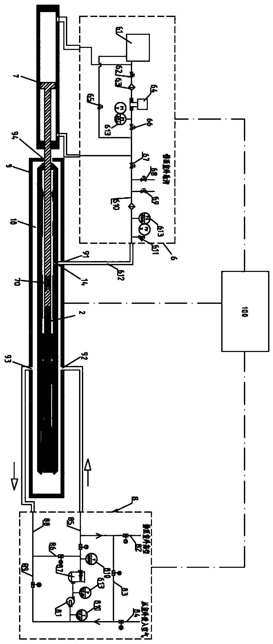
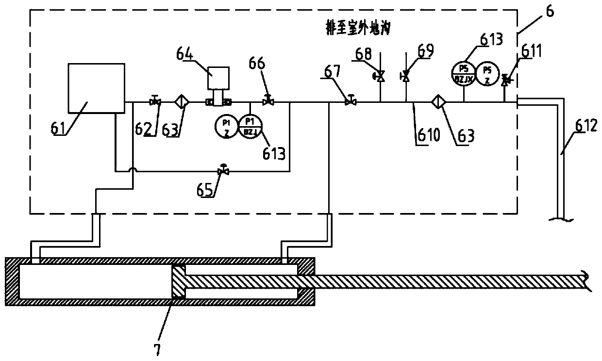
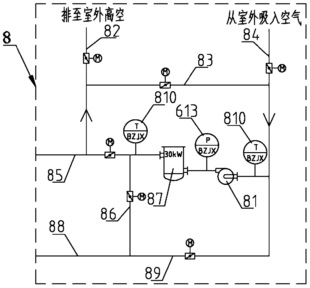
[0038] Such as figure 1 , 2 , 3, the fidelity coring device high-pressure high-temperature simulation experiment system disclosed in this embodiment includes a pressure supply unit 6 , a heat source supply unit 8 , a high-temperature and high-pressure chamber, a data acquisition unit and a control unit 100 . The high temperature and high pressure chamber includes a thermostat 9 and a pressure experiment chamber 10 placed in the thermostat 9. The thermostat 9 is provided with a medium inlet 92, a medium outlet 93 and a first reserved hole 91 for the test pipeline to pass through. The positions of the medium inlet 92 and the medium outlet 93 are set as required. In this embodiment, the medium inlet 92 and the medium outlet 93 are set on opposite sides of the incubator 9 .

[0039] The pressure supply unit 6 is connected to the pressure test chamber 10 through pipelines to adjust the pressure in the pressure chamber 2, so as to realize the simulation of the high-pressure environ...

Embodiment approach 2

[0077] In Embodiment 1, the pressure-holding experimental cabin is connected to the hydraulic pipeline by drilling holes in the cylinder wall, and the drilling of the drilling rig will damage the pressure-holding experimental cabin, thereby making the experimental results unreliable.

[0078] Such as Figure 8 , 9 , 10, the cabin body of the pressure test cabin 10 in the present embodiment comprises the first test piece 11, the second test piece 12 and the intermediate connector 13, the first test piece 11 is the outer cylinder 1 upper end of the pressure-holding test cabin, The second experimental piece 12 is the lower end of the outer cylinder 1 of the pressure-holding experimental cabin, and the intermediate connecting piece 13 is a cylindrical structure; the first experimental piece 11 and the second experimental piece 12 are connected through the intermediate connecting piece 13, and the liquid injection hole 14 is arranged in the middle The cylinder wall of the connecti...

Embodiment approach 3

[0084] The difference between this embodiment and the first and second embodiments is that the heat source supply unit 8 is different. Such as Figure 11 As shown, the heat source supply unit 8 in this embodiment includes a liquid supply system and an electric heater 805. The liquid supply system includes an oil tank 801 and a pump 802. The outlet of the oil tank 801 is connected to the inlet of the pump 802, and the outlet of the pump 802 is connected to the electric heater. 805 is connected to the inlet, and the outlet of the electric heater 805 is connected to the medium inlet 92 of the thermostat 9 through the liquid inlet pipeline 803 .

[0085] The medium outlet 93 of the thermostat 9 is connected to one end of the liquid outlet pipeline 804 , and the other end of the liquid outlet pipeline 804 is connected to the oil tank 801 . The connecting pipeline between the pump 802 and the electric heater 805 is provided with a filter, a pressure gauge, a safety valve 611 and an...


PUM


Abstract

The invention relates to a high-pressure and high-temperature simulation experiment system for a fidelity coring device. The system comprises a pressure supply unit, a heat source supply unit, a high-temperature and high-pressure cabin, a data acquisition unit and a control unit. The high-temperature and high-pressure cabin comprises a temperature box and a pressure experiment cabin arranged in the temperature box, and the temperature box is provided with a medium inlet, a medium outlet and a first preformed hole for an experiment pipeline to penetrate through. The pressure supply unit is connected with the pressure experiment cabin through a pipeline so as to adjust the pressure in the pressure cabin. The heat source supply unit is connected with the incubator through a pipeline to adjustthe temperature of the pressure experiment cabin, and the pressure supply unit, the heat source supply unit and the data acquisition unit are all connected with the control unit. The pressure supplyunit and the heat source supply unit are arranged, the high-temperature and high-pressure environment can be simulated, the pressure maintaining capacity of the pressure maintaining experiment cabin under the high-temperature and high-pressure conditions can be verified, the experiment integrity can be improved, the defects of the fidelity cabin of the coring device can be better found, and therefore the fidelity cabin of the coring device can be better improved.

Description

technical field [0001] The invention relates to the technical field of coring experiment devices, in particular to a high-pressure and high-temperature simulation experiment system for a fidelity coring device. Background technique [0002] The physical, mechanical, chemical and biological properties of deep rocks are closely related to their in-situ environmental conditions. The loss of in-situ environment during the coring process will lead to irreversible distortion of the physical, chemical and mechanical properties of the core. The core and key of the research is How to obtain in-situ cores under deep environmental conditions, and perform real-time loading tests and analysis under in-situ fidelity. [0003] After the drilling rig obtains the sample, it needs the pressure maintaining control device of the fidelity chamber to maintain the pressure and seal the sample. The pressure-holding performance of the fidelity chamber needs to be continuously verified and improved ...

Claims


Application Information

Patent Timeline
IPC IPC(8): G01N1/08
CPCG01N1/08
Inventor 谢和平高明忠陈领吴年汉李聪李佳南何志强杨明庆胡云起刘贵康
Owner SHENZHEN UNIV
Learn More