Device and method for carrying out stress corrosion experiment in high-temperature liquid-phase corrosion environment

A technology for stress corrosion and corrosive environments, applied in measuring devices, using stable tension/pressure testing materials, instruments, etc. precise control, etc.

Pending Publication Date: 2020-08-07
西安稀有金属材料研究院有限公司
View PDF10 Cites 1 Cited by
  • Summary
  • Abstract
  • Description
  • Claims
  • Application Information

AI Technical Summary

Problems solved by technology

[0004] At present, the stress corrosion test methods for metal materials in high temperature liquid phase environment are mainly relatively simple U-shaped bending test and C-shaped ring test. Stress Corrosion Experimental Method in High Temperature Water", but this kind of method only provides a rough stress corrosion performance evaluation scheme, which cannot realize the precise control of stress, let alone obtain the critical stress and crack growth rate of metal materials under stress corrosion conditions. The key performance indicators and experimental results are far less reliable than the slow strain rate tensile test. In addition, the current stress corrosion test methods for high-temperature liquid-phase environments are mostly water and salt solutions, while for corrosive liquid-phase (such as strong acid, strong alkali) metal material stress corrosion experimental test, there is no mature test method at present, in addition, although there are methods and devices for carrying out stress corrosion experiments using universal testing machines in the prior art, but in the prior art The devices and methods used are not suitable for stress corrosion performance testing in high-temperature liquid-phase corrosive environments

Method used


Image

  • Device and method for carrying out stress corrosion experiment in high-temperature liquid-phase corrosion environment
  • Device and method for carrying out stress corrosion experiment in high-temperature liquid-phase corrosion environment
  • Device and method for carrying out stress corrosion experiment in high-temperature liquid-phase corrosion environment

Examples


Embodiment 1

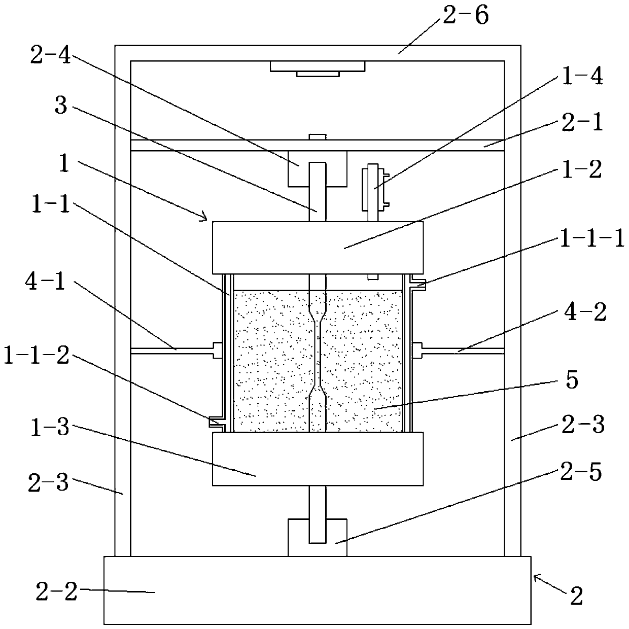
[0045] Such as figure 1 , figure 2 , image 3 and Figure 4 As shown, the device for performing stress corrosion experiments in the high-temperature liquid phase corrosion environment of this embodiment includes a universal testing machine 2 and a stress corrosion test chamber 1 connected to the universal testing machine 2 through a clamp. The machine 2 includes a workbench 2-2 and two columns 2-3 respectively arranged on the two ends of the table top of the workbench 2-2, and the tops of the two columns 2-3 are connected with the two ends of the fixed beam 2-6 respectively A moving beam 2-1 for loading the stress corrosion test sample 3 is arranged between the upright columns 2-3, and an upper chuck 2-1 connected to the upper end of the stress corrosion test sample 3 is arranged on the moving beam 2-1. 4. The workbench 2-2 is provided with a lower chuck 2-5 connected to the lower end of the stress corrosion test sample 3, and the holder includes a first holder symmetrical...

Embodiment 2

[0057] This embodiment includes the following steps:

[0058] Step 1, process the zirconium alloy metal rod to obtain the experimental rod, the structure and size of which are shown in Figure 5 ;

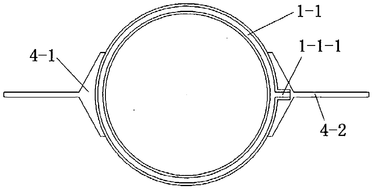
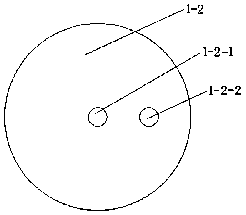
[0059] Step 2: Clamp and connect the first clamper 4-1 and the second clamper 4-2 provided on the column 2-3 of the universal testing machine 2 to the middle part of the double-layer glass cylinder 1-1. The lower end of the double-layer glass cylinder 1-1 is sealed and connected with the lower plug 1-3, and the short connecting section 3-2 of the experimental rod obtained in step 1 is inserted into the lower plug sample of the lower plug 1-3. Hole 1-3-1 and keep it sealed, inject the nitric acid solution with a mass concentration of 6mol / L into the double-layer glass cylinder 1-1, keep the rod gauge section 3-3 of the experimental rod completely immersed in the nitric acid solution, The upper end of the double-layer glass cylinder 1-1 is sealed and connected with the upper plug h...

Embodiment 3

[0066] This embodiment includes the following steps:

[0067] Step 1, process the 304L stainless steel metal plate to obtain the experimental plate;

[0068] Step 2: Clamp and connect the first clamper 4-1 and the second clamper 4-2 provided on the column 2-3 of the universal testing machine 2 to the middle part of the double-layer glass cylinder 1-1. The lower end of the double-layer glass cylinder 1-1 is sealed and connected to the lower plug 1-3, and the short clamping section 3-6 of the experimental plate obtained in step 1 is inserted into the lower plug sample of the lower plug 1-3 Through the hole 1-3-1 and keep it sealed, inject the nitric acid solution with a mass concentration of 8mol / L into the double-layer glass cylinder 1-1, and keep the plate gauge section 3-7 of the test plate completely immersed in the nitric acid solution , the upper end of the double-layer glass cylinder 1-1 is sealed with the upper plug 1-2, and the long clamping section 3-8 of the experime...


PUM

PropertyMeasurementUnit
heightaaaaaaaaaa
thicknessaaaaaaaaaa

Abstract

The invention discloses a device for carrying out a stress corrosion experiment in a high-temperature liquid-phase corrosion environment. The device comprises a universal testing machine and a stresscorrosion experiment box clamped with the universal testing machine through a clamper; the stress corrosion experiment box comprises a double-layer glass cylinder, and an upper plug and a lower plug which are hermetically connected with the double-layer glass cylinder; an upper plug sample through hole and a condensing device through hole matched with the condensing device are formed in the upperplug, a lower plug sample through hole is formed in the lower plug, and the upper plug sample through hole and the lower plug sample through hole are connected with the stress corrosion experiment sample in a sealed mode. Besides, the invention also discloses a stress corrosion experiment method, and the method comprises the following steps: loading a stress corrosion experiment sample and corrosive liquid into the stress corrosion experiment box by using a universal testing machine to obtain the loaded experiment sample and data. According to the invention, the universal testing machine is prevented from being contacted with corrosive liquid, a stress corrosion experiment is carried out in a high-temperature liquid-phase corrosion environment, and accurate loading and real-time observation can be realized.

Description

technical field [0001] The invention belongs to the technical field of stress corrosion performance testing, and in particular relates to a device and method for performing stress corrosion experiments in a high-temperature liquid phase corrosion environment. Background technique [0002] The metal erosion caused by the simultaneous action of corrosive environment and static tensile stress often leads to the formation of cracks, resulting in a significant decline in the bearing capacity of metal structures. [0003] There are various methods for evaluating the stress corrosion performance of metals. In some cases, each method has its own special advantages. Before making a stress corrosion test plan, it must be decided which method is suitable for the test. Depending on the purpose of the experiment and the information required, some experiments are only valuable to the plant engineer and try to replicate the active service conditions as much as possible. Simpler experimenta...

Claims


Application Information

Patent Timeline
Patent Type & Authority Applications(China)
IPC IPC(8): G01N3/18G01N3/02
CPCG01N3/18G01N3/02G01N2203/0003G01N2203/0017G01N2203/024G01N2203/0226
Inventor 刘承泽张于胜吴金平潘晓龙赵彬徐建平
Owner 西安稀有金属材料研究院有限公司
Why Eureka
Try Eureka