
Power amplifier with heat dissipation structure

A technology of power amplifier and heat dissipation structure, applied in power amplifier and other directions, can solve the problems of inconvenient connection, high production cost, circuit short circuit, etc., to ensure the heat dissipation function and effect, improve the heat dissipation effect, and the effect of fast heat dissipation

Pending Publication Date: 2020-08-07
SHANGHAI MUNICIPAL ELECTRIC POWER CO +1
View PDF0 Cites 1 Cited by
  • Summary
  • Abstract
  • Description
  • Claims
  • Application Information

AI Technical Summary

Problems solved by technology

The existing practice is to place the power amplifier in the cabinet, use the cabinet fan to circulate the air, and also use the humidifier to increase the ambient humidity and use the moisture in the air to take away more heat. The work will also fail; and the humidifier will increase the air moisture and easily cause a short circuit in the circuit, which is a safety hazard
[0003] Another method is to use the heat conduction device to dissipate heat from the chassis. In this way, the heat conduction device is used to connect the power amplifier to the chassis. It is necessary to add heat dissipation sheets on the outer wall of the chassis, which increases the footprint of the chassis. The heat conduction device uses heat pipes. The production cost is high, and it is inconvenient to connect. The thermal fluid is used as a heat dissipation medium, and it is not convenient to replace it in time after the temperature rises.

Method used


Image

  • Power amplifier with heat dissipation structure

Examples


Embodiment 1

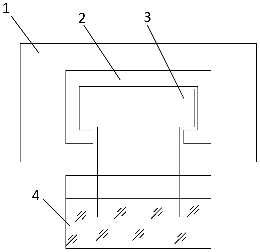
[0027] Such as figure 1 As shown, a power amplifier with a heat dissipation structure includes a power amplifier main body 1, a fixed frame 2, a heat dissipation strip 3 and a heat dissipation medium container 4, the fixed frame 2 is arranged on the outer wall of the power amplifier main body 1, and one end of the heat dissipation strip 3 is fixed In the fixed frame 2 and attached to the outer wall of the power amplifier main body 1, the other end is soaked in the heat dissipation medium container 4, the heat dissipation medium in the heat dissipation medium container 4 forms a capillary phenomenon with the heat dissipation strip 3, and the heat dissipation medium volatilizes from the heat dissipation strip 3 Take away the heat generated by the power amplifier. If necessary, add an electric fan nearby to increase the air flow rate and enhance the heat dissipation effect.

[0028] The heat dissipation strip 3 is provided with an insulating layer on the side of the outer wall o...

Embodiment 2

[0035] Different from Embodiment 1, the fixing frame 2 and the main body of the power amplifier 1 are adhered by self-adhesive, such as 3M adhesive tape, which will not leave sticking marks.

Embodiment 3

[0037] The difference from Embodiment 1 is that the heat dissipation strip 3 is made of hard material, such as a thick metal microporous plate, and the internal holes have capillarity. When the main body of the power amplifier 1 is overhead, the heat dissipation strip of this material can be selected. The material is also more thermally conductive.


PUM


Abstract

The invention relates to a power amplifier with a heat dissipation structure. The power amplifier comprises a power amplifier main body (1), a fixed frame (2), a heat dissipation strip (3) and a heatdissipation medium container (4), wherein the fixed frame (2) is arranged on the outer wall of the power amplifier main body (1); one end of the heat dissipation strip (3) is fixed in the fixed frame(2) and is attached to the outer wall of the power amplifier main body (1), the other end of the heat dissipation strip (3) is soaked in the heat dissipation medium container (4), a heat dissipation medium in the heat dissipation medium container (4) and the heat dissipation strip (3) form a capillary phenomenon, and the heat dissipation medium volatilizes from the heat dissipation strip (3) to take away heat generated by the power amplifier. Compared with the prior art, the capillary phenomenon is formed by the heat dissipation medium and the heat dissipation strip, the heat dissipation medium volatilize from the heat dissipation strip to take away heat generated by the power amplifier, the heat dissipation speed is high, the heat dissipation function and effect can be guaranteed by adding the heat dissipation medium, the connection is convenient, heat dissipation pipes do not need to be used, and maintenance is avoided.

Description

technical field [0001] The invention relates to a power amplifier, in particular to a power amplifier with a heat dissipation structure. Background technique [0002] The power amplifier will have heat problems after running for a long time, so it needs to be equipped with a good heat dissipation space. The existing practice is to place the power amplifier in the cabinet, use the cabinet fan to circulate the air, and also use the humidifier to increase the ambient humidity and use the moisture in the air to take away more heat. The work will also fail; and the humidifier will increase the air moisture and easily cause a short circuit in the circuit, which is a safety hazard. [0003] Another method is to use the heat conduction device to dissipate heat from the chassis. In this way, the heat conduction device is used to connect the power amplifier to the chassis. It is necessary to add heat dissipation sheets on the outer wall of the chassis, which increases the footprint o...

Claims


Application Information

Patent Timeline
Patent Type & Authority Applications(China)
IPC IPC(8): H03F3/20
CPCH03F3/20
Inventor 沈冰陈冉傅晓飞纪坤华周德生邹晓峰庄黎明杜炤鑫冯倩
Owner SHANGHAI MUNICIPAL ELECTRIC POWER CO
Learn More