Quick fertilizer applicator with quantitative control function

A quantitative control and fertilizer applicator technology, applied in fertilization devices, fertilizer distributors, applications, etc., can solve problems such as time-consuming and labor-intensive, and achieve the effect of increasing the contact area

Pending Publication Date: 2020-08-11
刘强
View PDF8 Cites 0 Cited by
  • Summary
  • Abstract
  • Description
  • Claims
  • Application Information

AI Technical Summary

Problems solved by technology

[0004] In order to overcome the time-consuming and labor-intensive shortcomings of people needing to bend down and pour the fertilizer into the well-dug pits in the process of applying fertilizer, the technical problem is to provide a method that people do not need

Method used


Image

  • Quick fertilizer applicator with quantitative control function
  • Quick fertilizer applicator with quantitative control function
  • Quick fertilizer applicator with quantitative control function

Examples


Embodiment 1

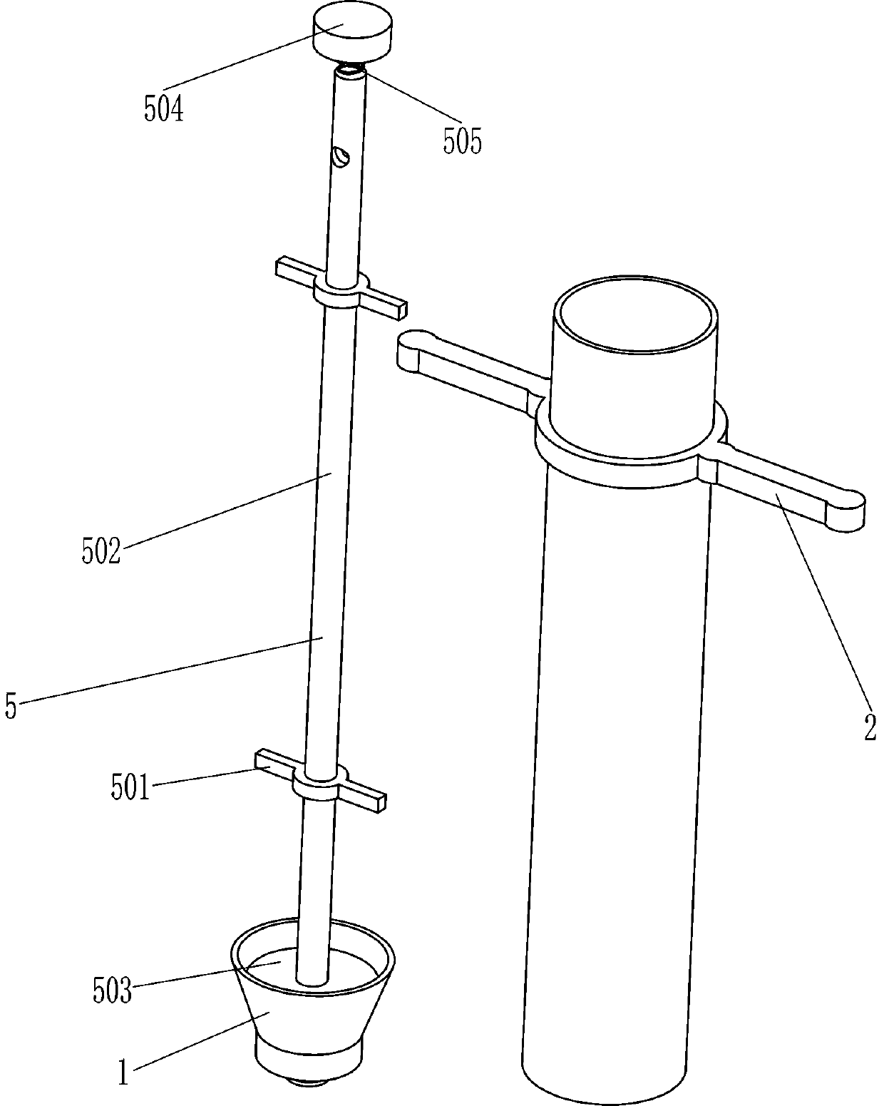
[0022] A rapid fertilizer applicator with quantitative control, such as figure 1 As shown, it includes a long barrel 1, a handle 2 and a discharge device 5, the top of the long barrel 1 is provided with a handle 2, and the long barrel 1 is provided with a discharge device 5.

[0023] When people need to apply fertilizer, first people place this equipment on the place where fertilization is needed. When the bottom of the discharge device 5 is in contact with the land, the discharge device 5 will move upwards. At this time, the fertilizer will fall out from the bottom of the long barrel 1. When the fertilizer is applied, people lift up the device. At this time, the bottom of the discharge device 5 is separated from the land, and the discharge device 5 will move downward. Tight contact occurs between the bottom of the discharge device 5 and the bottom of the long barrel 1, so that the fertilizer will not fall out, so that fertilization can be completed.

Embodiment 2

[0025] On the basis of Example 1, such as Figure 1-3 As shown, the discharge device 5 includes a guide sleeve 501, a guide rod 502, a circular baffle 503, a support frame 504 and a first compression spring 505, and the long barrel 1 is vertically provided with a guide sleeve 501, which slides in the guide sleeve 501. There is a guide rod 502 connected in the same way, the lower part of the guide rod 502 is provided with a circular baffle 503, the circular baffle 503 is attached to the inner wall of the lower part of the long barrel 1, and a support frame 504 is provided in the middle of the rear part of the handle 2, and the upper part of the support frame 504 is located on the guide Above the rod 502 , a first compression spring 505 is connected between the support frame 504 and the guide rod 502 .

[0026] When people need to fertilize, align the long barrel 1 with the place where fertilization is needed, then press it down with your hands, the bottom of the guide rod 502 c...

Embodiment 3

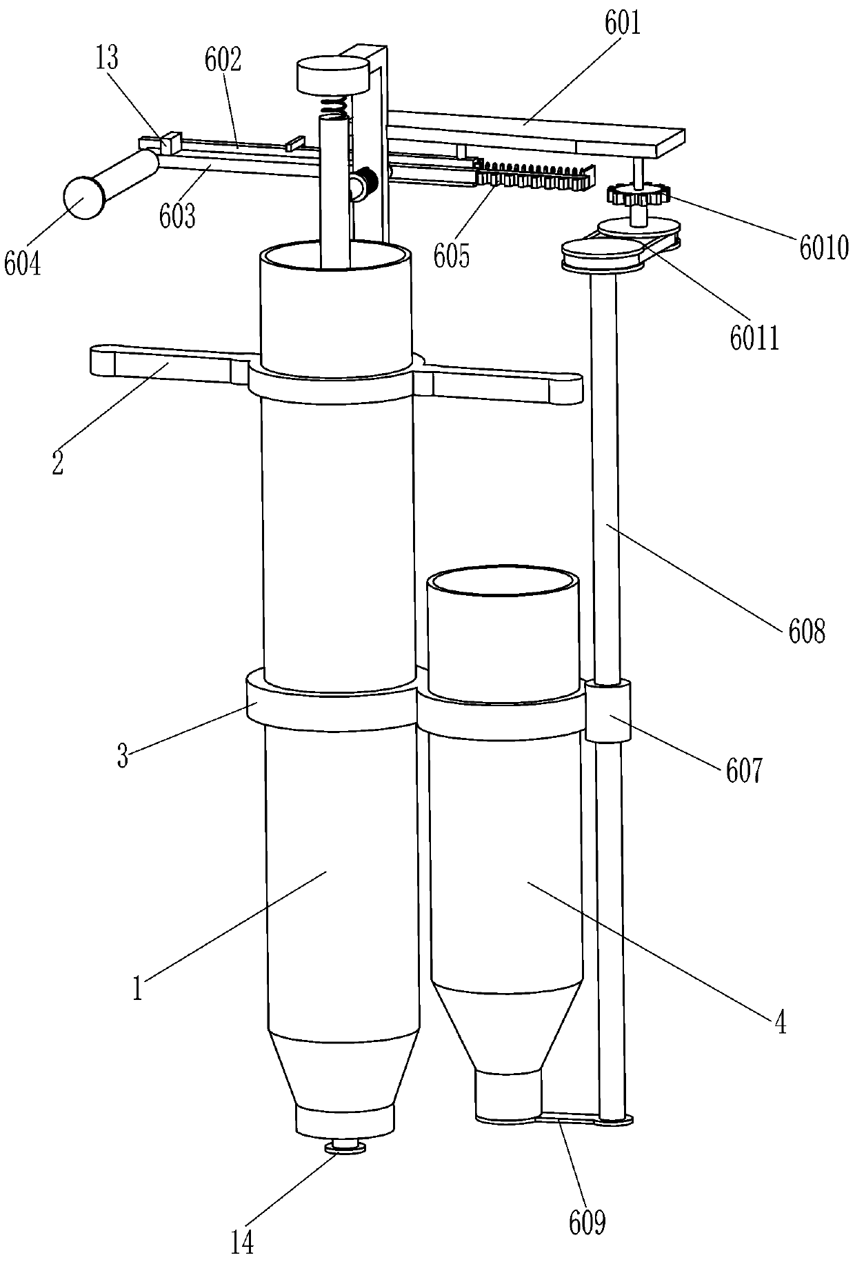
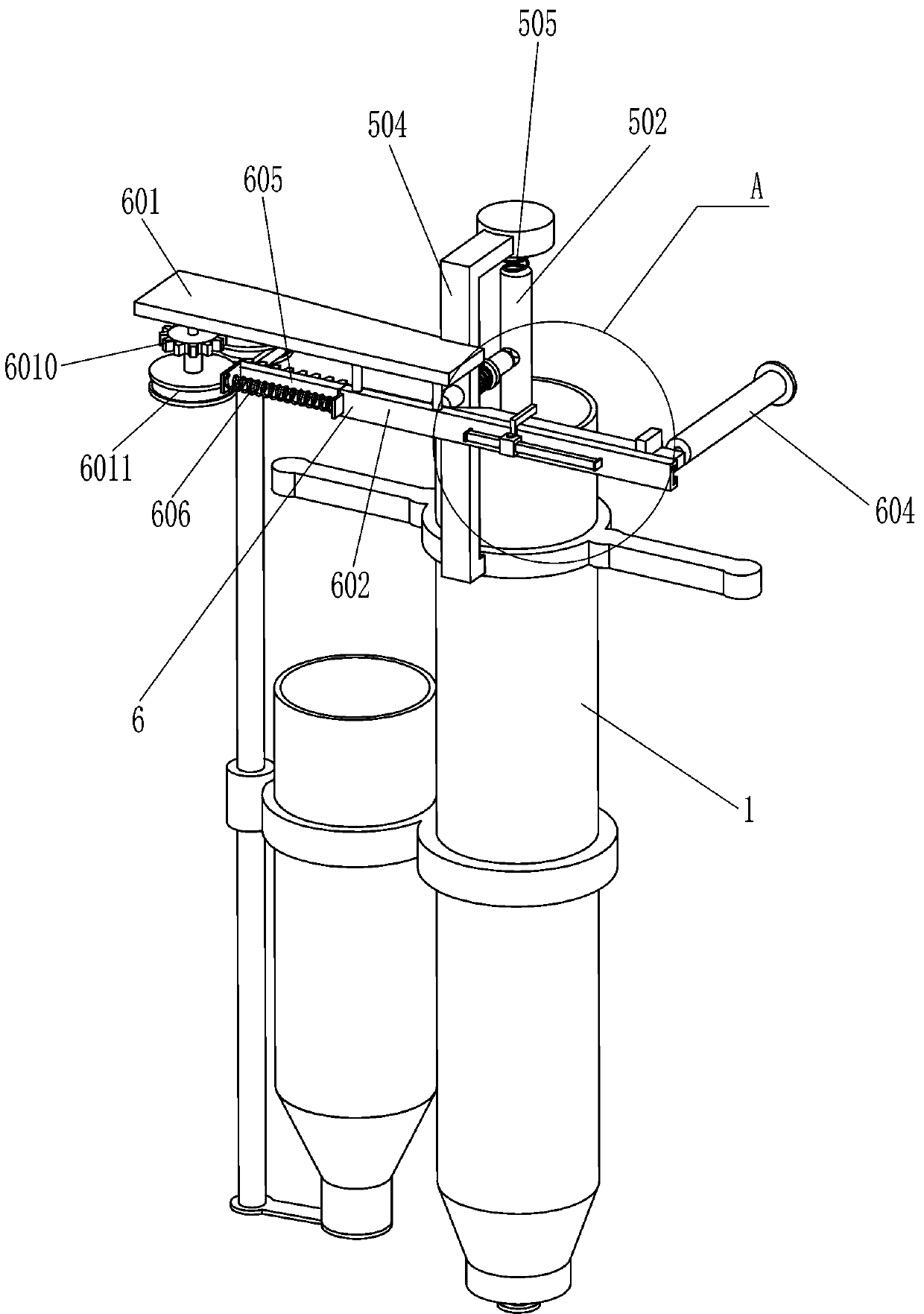
[0032] On the basis of Example 2, such as figure 2 and Figure 4 As shown, the discharge speed control device also includes a rack 605, a second compression spring 606, a driving gear 6010, and a belt transmission assembly 6011. The right end of the arc panel 603 is connected to the rack 605, and the right wall of the rear part of the rack 605 is connected to the slide rail. A second compression spring 606 is connected between 602, a drive gear 6010 is rotatably connected to the bottom right side of the mounting plate 601, and a belt transmission assembly 6011 is connected to the rotating shaft 608 and the drive gear 6010.

[0033]When people need to control the discharge, they can use the short barrel 4 to fertilize. People push the handle 604 to the right with their hands, and the movement of the handle 604 to the right drives the arc panel 603 to move to the right. When the arc panel 603 moves to the right When in contact with the clamping rod 7, the third compression spr...


PUM


Abstract

The invention relates to a fertilizer applicator, in particular to a quick fertilizer applicator with a quantitative control function. The technical problem to be solved by the invention is to providethe quick fertilizer applicator which can apply fertilizer by manually operating equipment without bending down and can control the fertilizer application amount, so that the fertilizer can be conveniently saved, and the operation is simple and easy. The quick fertilizer applicator with the quantitative control function comprises a long charging barrel, a grab handle and a discharging device, wherein the grab handle is arranged on the upper portion of the long charging barrel; the discharging device is arranged in the long charging barrel. People control the fertilizer application amount by adjusting the position of an L-shaped strip, push a pull handle to move rightwards to drive an arc-shaped plate and a square strip to move rightwards, and when the square strip moves rightwards to makecontact with the L-shaped strip, the arc-shaped plate and a rack are prevented from moving rightwards, so that the rotation degree of a driving gear can be controlled, and the situation that people exert too much force to enable a second baffle to rotate and an opening of a short charging barrel is too large, and consequently the fertilizer consumption is too high is avoided.

Description

technical field [0001] The invention relates to a fertilizer applicator, in particular to a quantitatively controllable rapid fertilizer applicator. Background technique [0002] At present, before planting plants, people need to dig pits and apply fertilizers to the soil. Among them, they need to bend down manually to pour the fertilizers into the dug pits, which will cause people's backaches and consume people's physical strength. Fertilizer is easily wasted, so troublesome and laborious. [0003] In order to solve the problems that people have in applying fertilizer, we have developed a kind of fertilizer that people don't need to bend over to apply fertilizer, and can apply fertilizer by manually operating the equipment, and can control the amount of fertilizer applied, which is convenient and can save fertilizer, and the operation is simple and easy The rapid fertilizer applicator that can be controlled quantitatively overcomes the time-consuming and labor-intensive sh...

Claims


Application Information

Patent Timeline
IPC IPC(8): A01C15/02
CPCA01C15/02
Inventor 刘强
Owner 刘强
Why Eureka
Try Eureka