Hip joint rotation center locator

A technology of rotation center and center positioning hole, which is used in stereotaxic surgical instruments, medical science, bone drill guidance, etc. low effect

Active Publication Date: 2020-08-11
郑州市骨科医院
View PDF7 Cites 2 Cited by
  • Summary
  • Abstract
  • Description
  • Claims
  • Application Information

AI Technical Summary

Problems solved by technology

[0004] The purpose of the present invention is to provide a locator for the center of rotation of the hip joint to solve the various methods for indirect measurement of the center of rotation proposed in the above-mentioned background technology. A

Method used


Image

  • Hip joint rotation center locator
  • Hip joint rotation center locator
  • Hip joint rotation center locator

Examples


Embodiment Construction

[0019] The following will clearly and completely describe the technical solutions in the embodiments of the present invention with reference to the accompanying drawings in the embodiments of the present invention. Obviously, the described embodiments are only some, not all, embodiments of the present invention. Based on the embodiments of the present invention, all other embodiments obtained by persons of ordinary skill in the art without making creative efforts belong to the protection scope of the present invention.

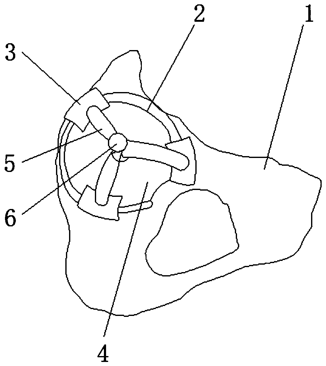
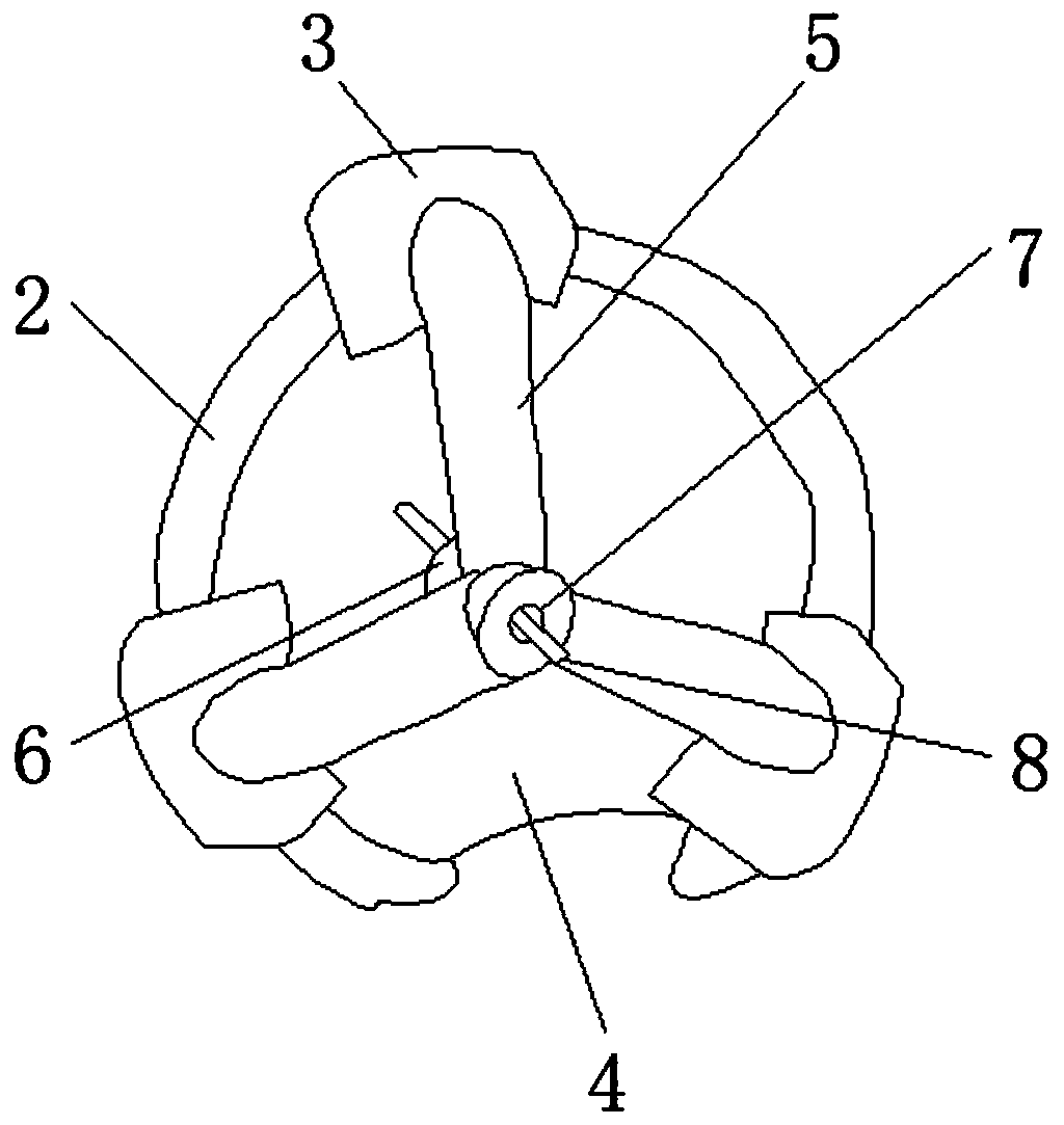
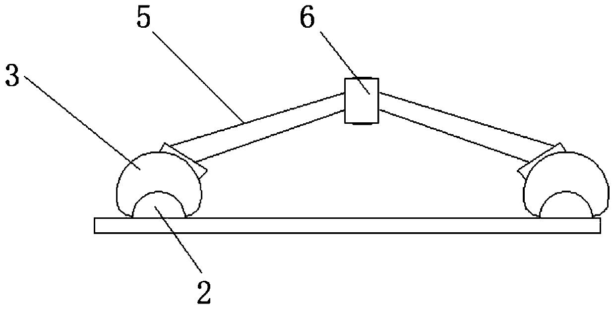
[0020] see Figure 1-3 , the present invention provides a technical solution: a hip joint rotation center locator, the upper end surface of the acetabular body 1 is the acetabular edge and is the acetabular edge 2, and the outer surface of the acetabular edge 2 is connected with a fixed foot 3, the fixed foot The upper end surface of 3 is fixed with a connecting strut 5, and the connecting pile body 6 is fixed on the upper end surface of the connecting strut 5...


PUM


Abstract

The invention discloses a design thought and an application method of a hip joint rotation center locator. The rotation center locator comprises a connecting pile body movably fixed to the edge of acetabulum, wherein the upper end face of an acetabulum body is the edge of the acetabulum, namely the acetabulum edge, fixing feet are connected to the outer surface of the acetabulum edge, and a connecting supporting rod is fixed to the upper end face of each fixing foot; the inner side of the acetabulum edge is an acetabulum center location area, and the position of a hip joint rotation center isdetermined through the arrangement of a center location hole according to an indication guide pin track. The hip joint rotation center locator is composed of the fixing feet, the connecting supportingrods and the connecting pile body; the acetabulum body, the acetabulum edge and the location area are normal anatomical positions; the influence of body position change of a patient on an intraoperative filing angle can be avoided through combination of the locator and the acetabulum; the hip joint rotation center is located in a physical structure mode; and the problems of large differences of located rotation centers among different operators and inaccurate positioning points due to different body types of the different patients are solved.

Description

technical field [0001] The invention relates to the technical field of CIP cleaning systems, in particular to a hip joint rotation center locator. Background technique [0002] Total hip arthroplasty has become the most effective treatment for advanced hip joint diseases, and clinicians have gradually gained a deeper understanding of the importance of reconstructing the center of rotation of the hip joint. Accurate reconstruction of the center of rotation can not only optimize the biomechanical environment around the hip joint, To improve the mobility of the hip joint, it is very important to restore the normal center of rotation during total hip replacement. However, the center of rotation is not a definite anatomical structure and can only be measured indirectly. [0003] At present, there are many methods for indirectly measuring the center of rotation, but there are few methods for clearly locating the center of rotation during surgery. Most of them are inferred based on...

Claims


Application Information

Patent Timeline
IPC IPC(8): A61B90/11A61B90/00A61B17/17
CPCA61B90/11A61B90/06A61B17/1735A61B17/1746A61B2017/564A61B2090/062
Inventor 王跃辉程慧曹亮亮邹士平郑伟
Owner 郑州市骨科医院
Why Eureka
Try Eureka