Automatic welding device for industrial fan mesh enclosure

An automatic welding and fan technology, applied in welding equipment, resistance welding equipment, metal processing equipment, etc., can solve problems such as low efficiency and high manual work pressure

Inactive Publication Date: 2020-08-11
罗峰
View PDF6 Cites 4 Cited by
  • Summary
  • Abstract
  • Description
  • Claims
  • Application Information

AI Technical Summary

Problems solved by technology

[0004] The purpose of the present invention is to solve the shortcomings of the existing industrial fan grille welding equipment that needs manual layout of ir

Method used


Image

  • Automatic welding device for industrial fan mesh enclosure
  • Automatic welding device for industrial fan mesh enclosure
  • Automatic welding device for industrial fan mesh enclosure

Examples


Embodiment 1

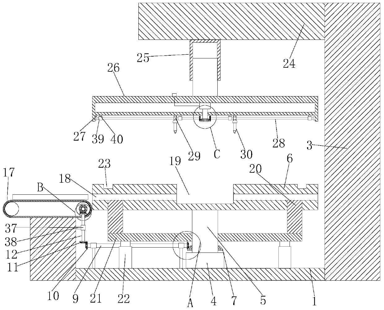
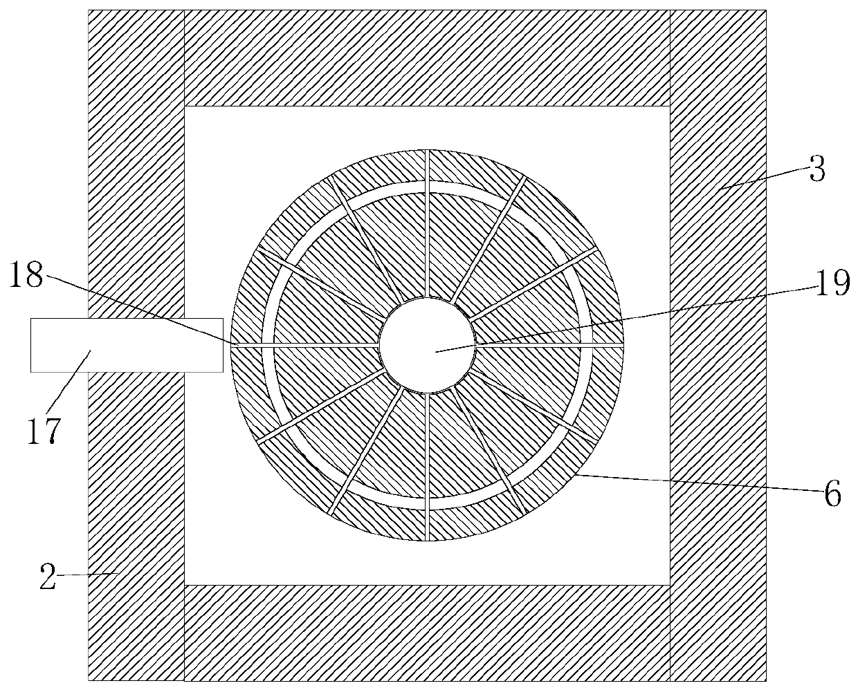
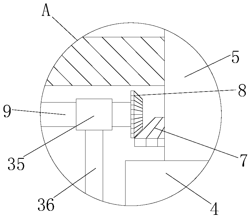
[0027] refer to Figure 1-5 , an automatic welding equipment for an industrial fan net cover, comprising a base plate 1, three side plates 2 and a column 3 are fixedly connected to the four sides of the base plate 1, and a motor 4 is fixedly connected to the center of the bottom inner wall of the base plate 1, and the motor 4 The output shaft is fixedly connected with the first roller 5, the top of the first roller 5 is fixedly connected with the welding mold 6, the first roller 5 is fixedly set with the first bevel gear 7, and the first bevel gear 7 is meshed with There is a second bevel gear 8, one side of the second bevel gear 8 is fixedly connected to one end of the second roller 9, and the other end of the second roller 9 is fixedly connected to the third bevel gear 10, and the third bevel gear 10 is meshed with A fourth bevel gear 11 is provided, and one end of the third roller 12 is fixedly connected to the top of the fourth bevel gear 11, and the other end of the third...

Embodiment 2

[0038] refer to Figure 1-5 , an industrial fan grille automatic welding equipment, including a bottom plate 1, the four sides of the bottom plate 1 are respectively fixed and welded with three side plates 2 and a column 3, the center of the bottom inner wall of the bottom plate 1 is fixedly connected with a motor 4, the motor A first roller 5 is fixedly welded on the output shaft of 4, a welding die 6 is fixedly welded on the top of the first roller 5, a first bevel gear 7 is fixedly sleeved on the first roller 5, and the first bevel gear 7 is A second bevel gear 8 is meshed, one side of the second bevel gear 8 is fixedly welded with one end of the second roller 9, the other end of the second roller 9 is fixedly welded with a third bevel gear 10, and the third bevel gear 10 A fourth bevel gear 11 is meshed on the top, one end of the third roller 12 is fixedly welded on the top of the fourth bevel gear 11, and the other end of the third roller 12 is fixedly welded with a fifth b...


PUM


Abstract

The invention belongs to the technical field of fan mesh enclosure welding device, and particularly relates to an automatic welding device for an industrial fan mesh enclosure. The automatic welding device comprises a bottom plate, wherein three side plates and a stand column are fixedly connected to the four side surfaces of the bottom plate separately; a motor is connected to the center of the inner wall of the bottom plate; a first rolling shaft is connected to an output shaft of the motor; a welding die is connected to the top of the first rolling shaft; a first bevel gear fixedly sleevesthe first rolling shaft; a second bevel gear is arranged on the first bevel gear in a meshing manner; and one side of the second bevel gear is connected with one end of a second rolling shaft. According to the automatic welding device disclosed by the invention, the second rolling shaft can be rotated through the first bevel gear and the second bevel gear while the first rolling shaft and the welding die are rotated by the motor; a third bevel gear on the second rolling shaft can rotate a third rolling shaft through a fourth bevel gear; and a fifth bevel gear on the third rolling shaft can rotate a central shaft and a roller through a sixth bevel gear, and then a conveying belt is rotated, so that an iron wire can enter a corresponding iron wire groove, and the automatic welding device isconvenient and effective.

Description

technical field [0001] The invention belongs to the technical field of welding equipment for fan nets, and in particular relates to automatic welding equipment for industrial fan nets. Background technique [0002] The mesh cover is a kind of metal wire fixed in front of various electrical appliances or metals to protect people from harm. The mesh cover is used in various electric fans, heaters, stoves and other mesh covers; electric ovens, refrigerator grids; oil Mesh baskets for frying pans, kitchen bathrooms, fruits, etc.; water dispenser cooling mesh; iron wire, stainless steel wire craft products, the traditional industrial fan grill production is to manually arrange the concentric iron rings of multiple fan grills on the jig , and the iron rings are welded together by a butt welding machine, which has the problems of low welding efficiency and high labor costs. [0003] Existing welding equipment for industrial fan grills needs manual layout of iron wires, and then we...

Claims


Application Information

Patent Timeline
IPC IPC(8): B23K11/00B23K11/36B21F27/10B23K101/22
CPCB21F27/10B23K11/008B23K11/36B23K2101/22
Inventor 罗峰
Owner 罗峰
Why Eureka
Try Eureka