Injection mold with water blowing device

A technology of injection molds and molds, which is applied in the field of injection molds with water blowing devices, can solve the problems of reducing the service life of molds, reducing production efficiency, and high labor intensity, so as to speed up production efficiency, reduce labor intensity, and reduce service life Effect

Inactive Publication Date: 2020-08-11
丁亮
View PDF0 Cites 9 Cited by
  • Summary
  • Abstract
  • Description
  • Claims
  • Application Information

AI Technical Summary

Problems solved by technology

[0003] In order to speed up the molding speed of the product, the current injection mold usually cools the product after it is molded. However, after the product is cooled, some moisture will remain in the water channel on the mold, which will easily cause the inside of the mold to rust for a long time and reduce the mold. In addition, after the product is formed in the mold, it is usually taken out manually, which is labor-intensive and reduces production efficiency

Method used


Image

  • Injection mold with water blowing device
  • Injection mold with water blowing device
  • Injection mold with water blowing device

Examples


Embodiment Construction

[0029] The technical solutions in the embodiments of the present invention will be clearly and completely described below in conjunction with the accompanying drawings in the embodiments of the present invention. Obviously, the described embodiments are only a part of the embodiments of the present invention, rather than all the embodiments.

[0030] In the description of the present invention, it should be understood that the terms "upper", "lower", "front", "rear", "left", "right", "top", "bottom", "inner", " The orientation or positional relationship indicated by “outside” is based on the orientation or positional relationship shown in the drawings, and is only for the convenience of describing the present invention and simplifying the description, and does not indicate or imply that the device or element referred to must have a specific orientation to The specific azimuth structure and operation cannot be understood as a limitation of the present invention.

[0031] Reference ...


PUM


Abstract

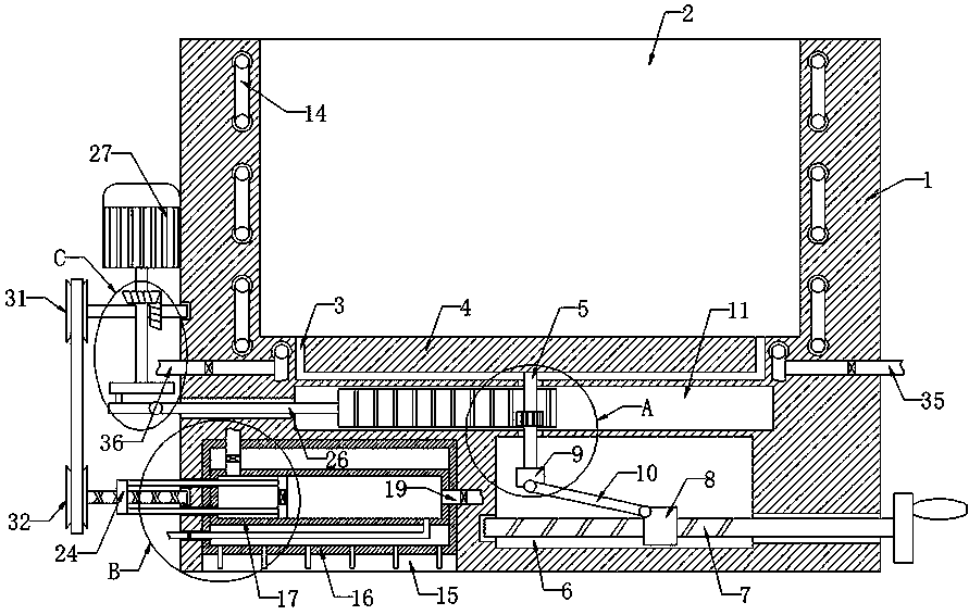
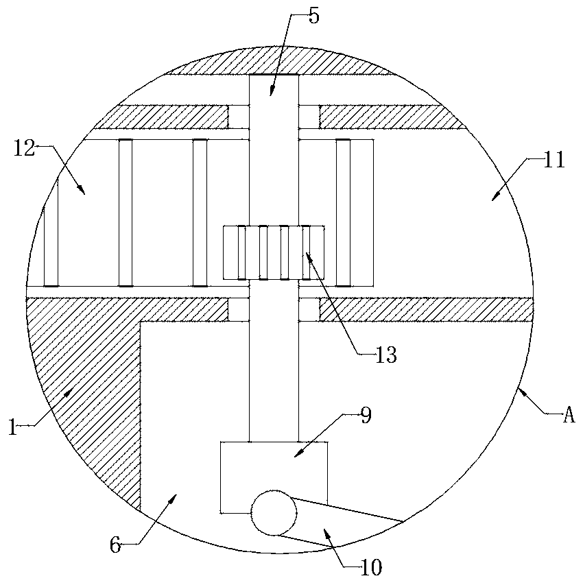
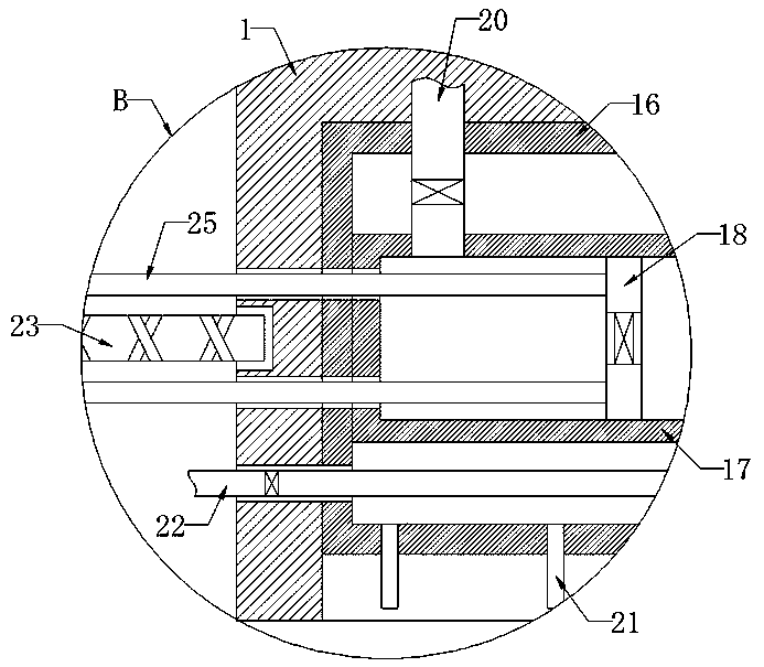
The invention discloses an injection mold with a water blowing device. The mold comprises a mold body, an injection molding groove is formed in the upper end of the mold body, a round groove is formedin the inner bottom of the injection molding groove, a disc is in sliding connection with the inner wall of the round groove, the lower end of the disc is fixedly connected with a vertical rod, a groove is formed in the side wall of the mold body, a screw is rotatably connected to the inner wall of the groove, a jacking mechanism for jacking the disc is mounted on the screw, a sliding groove is formed in the side wall of the mold body, a first driving mechanism used for driving the vertical rod to rotate is mounted in the sliding groove, the screw rotates to enable a sliding block to slide, through a connecting rod, the vertical rod is pushed to move upwards, the disc is further pushed to move upwards, a product on the disc is jacked out, the product can be conveniently taken out, when asingle-way sliding plate slides back and forth on the inner wall of a water storage box, water in the water storage box is continuously extruded to enter a cooling pipeline, continuous circulation ofthe water in the cooling pipeline can be achieved, and product cooling is quickened.

Description

Technical field [0001] The invention relates to the technical field of injection molds, in particular to an injection mold with a water blowing device. Background technique [0002] The injection mold is a device that injects the plastic melted by heat into the mold cavity at a high pressure by the injection molding machine, and the molded product is obtained after cooling and solidification. [0003] In order to speed up the molding speed of the product, the current injection mold often cools the product after it is molded. However, after the product is cooled, a part of the water will remain in the water channel on the mold, which will easily cause corrosion inside the mold for a long time and reduce the mold. In addition, after the product is formed in the mold, it is usually taken out manually, which is labor-intensive and reduces production efficiency. [0004] To this end, we propose an injection mold with a water blowing device. Summary of the invention [0005] The purpose o...

Claims


Application Information

Patent Timeline
Patent Type & Authority Applications(China)
IPC IPC(8): B29C45/26B29C45/40B29C45/73
CPCB29C45/2602B29C45/4005B29C45/73B29C45/7312
Inventor 丁亮
Owner 丁亮
Why Eureka
Try Eureka