Non-flaring guide pipe connector extrusion molding device

A technology for connecting extrusion and molding equipment, which is applied in the field of mechanical design and manufacturing, extrusion molding processing machinery design and manufacturing, can solve problems such as insufficient control, product pinching, and lack of support, so as to reduce labor intensity and solve replacement problems. Trouble, quality improvement effect

Active Publication Date: 2020-08-11
SICHUAN ZHONGZI TECH
View PDF17 Cites 0 Cited by
  • Summary
  • Abstract
  • Description
  • Claims
  • Application Information

AI Technical Summary

Problems solved by technology

In the specific implementation of this method, there are obvious defects: First, the clamp mechanism needs to manually operate the mechanical mold clamping during operation, and then drive the automatic mold clamping through the cylinder, which brings a great workload to the operators , this structure only realizes automatic mold clamping after mold clamping; secondly, in this mold clamping mode, the upper and lower clamps rely on their upper and lower mating surfaces to uniquely determine the mold clamping position, so the positions of the upper and lower clamps are always the same, In fact, different individual workpieces of the same theoretical specification will have differences in structural dimensions, and their outer diameters may be large or small, which will lead to some processing problems, such as interfering molds affecting mold clamping and causing products to be pinched , or the clamp is not tight, so that there is a gap between the workpiece and the cavity in the half-clamp mold located in the clamp, which cannot play a supporting role, so that during processing, the tube sleeve in the workpiece combination is squeezed under the internal expansion force of polyurethane Third, in the process of extruding polyurethane to realize conduit connection, the control of extrusion force is open. In fact, there will always be differences in structural dimensions between different workpieces. Polyurethane materials are used A certain number of times needs to be replaced, so each replaced individual has a difference in structural size and density, which means that for each specific processing catheter workpiece, the amount of compression and the movement stroke that needs to be squeezed are different. Usually The method is to use the pressure of the hydraulic system as the control quantity to realize the compensation for this difference. It is realized by setting a pressure sensor on the oil circuit of the hydraulic system to feed back to the system. Pressure, whose control is not direct and precise enough

Method used


Image

  • Non-flaring guide pipe connector extrusion molding device
  • Non-flaring guide pipe connector extrusion molding device
  • Non-flaring guide pipe connector extrusion molding device

Examples


Embodiment Construction

[0044] The present invention is further described below in conjunction with specific embodiment, and specific embodiment is the further description of the principle of the present invention, does not limit the present invention in any way, and the identical or similar technology of the present invention all does not exceed the scope of protection of the present invention.

[0045] In conjunction with the accompanying drawings.

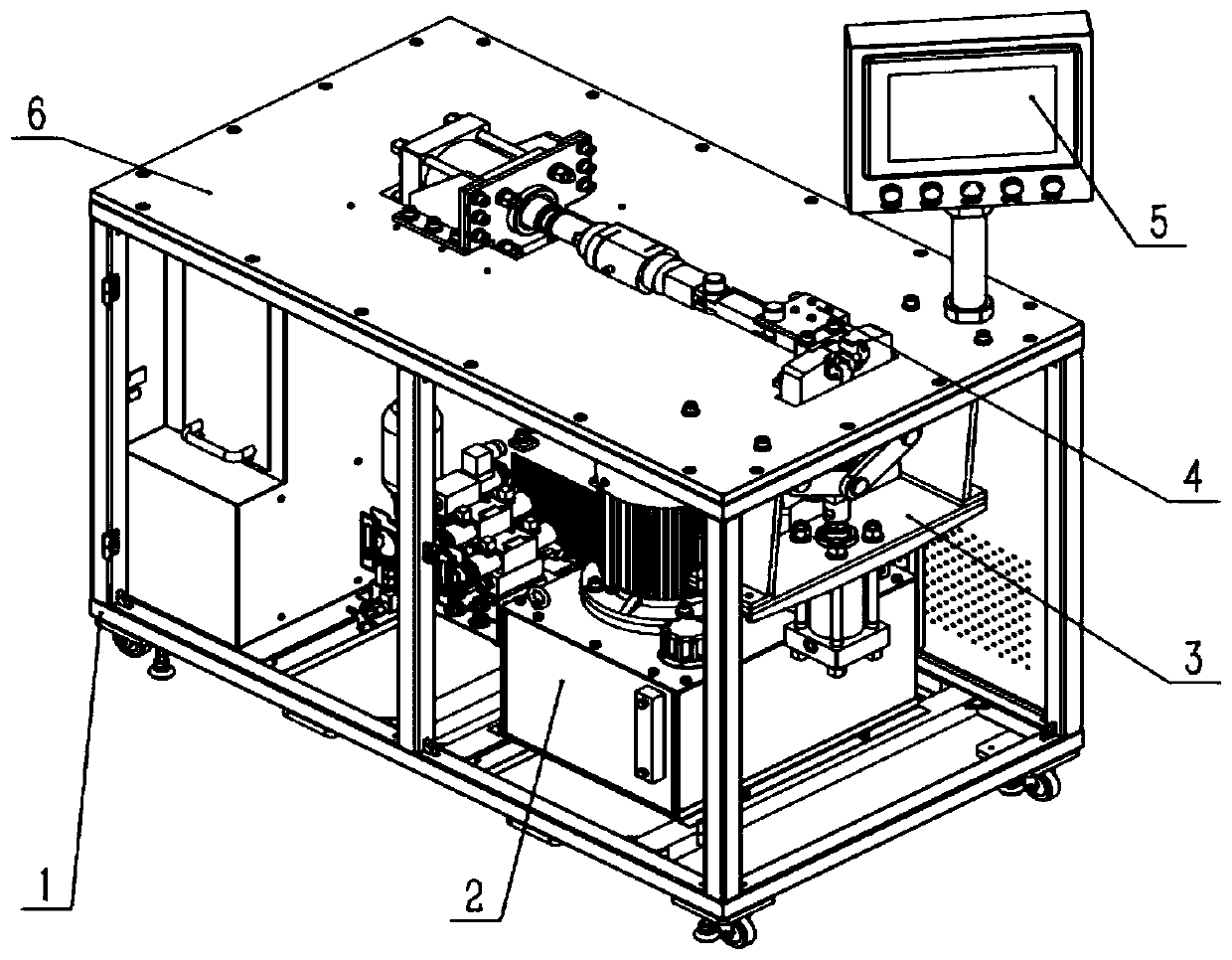
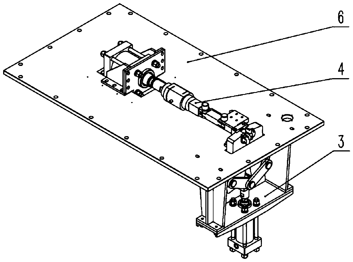
[0046] The equipment of the present invention includes a cabinet 1 , a hydraulic system 2 , a clamping mechanism 3 , a stretching mechanism 4 , an operation panel 5 and a working platform 6 .

[0047] The frame of the cabinet 1 is also provided with an electric control box 11 and a hydraulic system 2; both the electric control box 11 and the hydraulic system 2 are fixed in the frame of the cabinet 1 by screws or bolts; when necessary, the electric control box 11 and the hydraulic system 2 can be Take it out from the cabinet 1 frame during maintenance. ...


PUM


Abstract

The invention discloses a non-flaring guide pipe connector extrusion molding device. The device comprises a cabinet, a hydraulic system, a clamping mechanism, a stretching mechanism, an operation panel and a working platform; the hydraulic system provides power for the clamping mechanism and the stretching mechanism; the stretching mechanism comprises a stretching driving mechanism and an expanding mechanism, wherein the expanding mechanism comprises an adapter head, an anvil die, a half female die and a pull rod assembly centered on the same axis, the anvil die is provided with cylindrical cavity structures with four stages of diameters arranged in sequence, the half female die is a symmetrical structure formed by combining two semi-circular rings and is detachably mounted in a clamping arm of the clamping mechanism, and when the two semi-circular rings are combined, a die closing gap is formed at the combining portion. The device can effectively reduce the labor intensity of operators, for the size difference of different workpiece individuals with the same theoretical specification, can perform self-adaptive clamping, can realize direct closed-loop extrusion force control, improves the quality of produced products, solves the problems that die replacement is troublesome and requires a lot of tools for disassembling and assembling.

Description

technical field [0001] The invention belongs to the technical field of mechanical design and manufacture, in particular to the technical field of extrusion molding processing machinery design and manufacture, and in particular to an extrusion molding equipment for a non-flared conduit connector. Background technique [0002] In the prior art, the connection of the catheter connector is usually made by sealing a compressible elastic material with a certain volume, such as polyurethane material, in the processing space, and after extruding it to an incompressible stage, the catheter is deformed by polyurethane Partial extrusion produces plastic deformation, and the plastic deformation is extruded into the inner ring groove of the guide sleeve on the catheter, so that the catheter and the guide sleeve are tightly connected. [0003] The above-mentioned method is widely used for plastic processing and connection of non-flared conduits, and this processing method is adopted in th...

Claims


Application Information

Patent Timeline
Patent Type & Authority Applications(China)
IPC IPC(8): B29C65/56B29C65/78B29C65/00B29K75/00
CPCB29C65/56B29C65/7841B29C66/5221B29K2075/00
Inventor 王双飞唐良勇吴海东
Owner SICHUAN ZHONGZI TECH
Why Eureka
Try Eureka