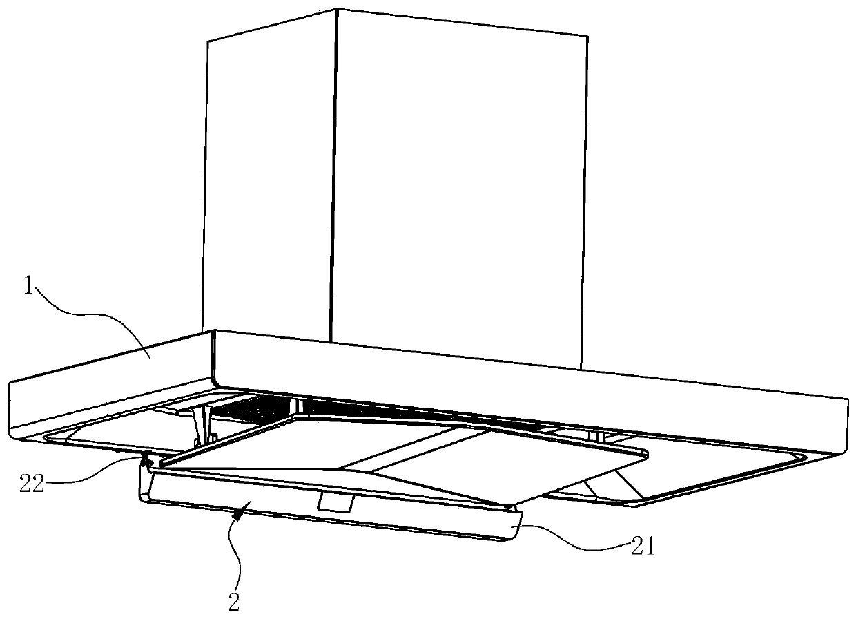
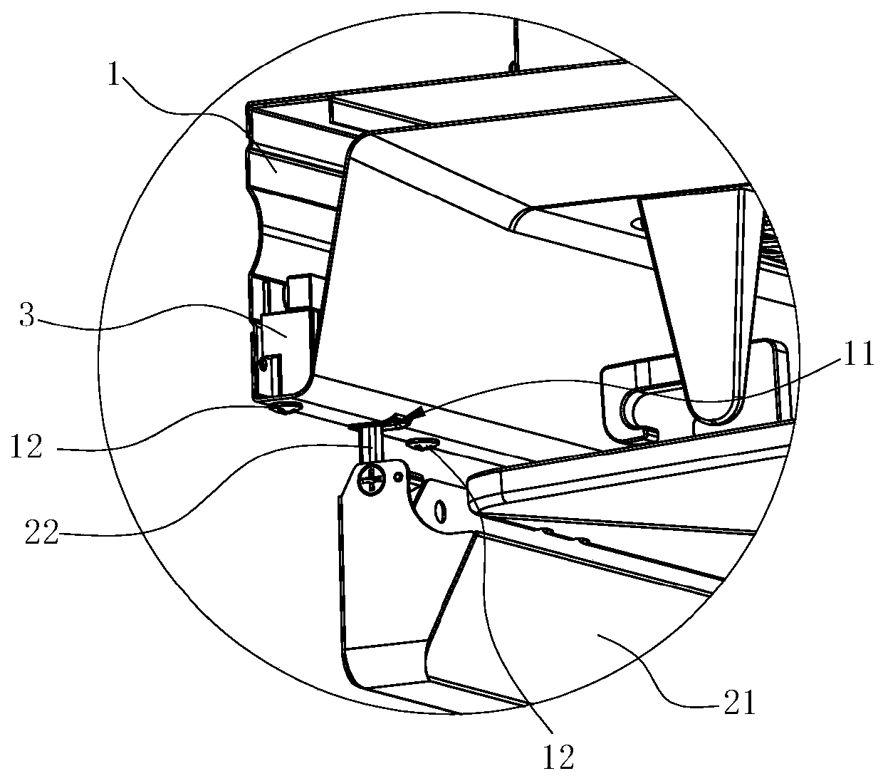
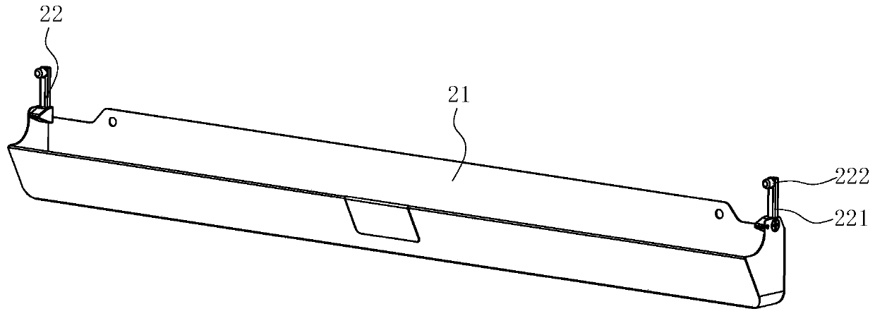
Oil cup mounting structure and range hood applying same

An installation structure and oil cup technology, applied in the application, removal of oil fume, household stoves, etc., can solve the problems of easy splashing, unstable disassembly, and difficult installation, so as to avoid waste oil splashing and oil cups. Damaged, easy-to-clean effect

Active Publication Date: 2020-08-11
NINGBO FOTILE KITCHEN WARE CO LTD
View PDF9 Cites 0 Cited by
  • Summary
  • Abstract
  • Description
  • Claims
  • Application Information

AI Technical Summary

Problems solved by technology

There are many problems in this installation method, for example, it is not easy to install because of the small plug-in port; it is not stable when dismantling, and it is easy to splash when the oil is too full. Under the action of gravity, the fixing structure on the other side will be damaged, resulting in problems such as the failure of the oil cup to be fixed

Method used


Image

  • Oil cup mounting structure and range hood applying same
  • Oil cup mounting structure and range hood applying same
  • Oil cup mounting structure and range hood applying same

Examples


Embodiment Construction

[0034] Embodiments of the present invention are described in detail below, examples of which are shown in the drawings, wherein the same or similar reference numerals denote the same or similar elements or elements having the same or similar functions.

[0035] In describing the present invention, it should be understood that the terms "center", "longitudinal", "transverse", "length", "width", "thickness", "upper", "lower", "front", " Back", "Left", "Right", "Vertical", "Horizontal", "Top", "Bottom", "Inner", "Outer", "Clockwise", "Counterclockwise", "Axial", The orientation or positional relationship indicated by "radial", "circumferential", etc. is based on the orientation or positional relationship shown in the drawings, and is only for the convenience of describing the present invention and simplifying the description, rather than indicating or implying the referred device or element must have a particular orientation, be constructed, and operate in a particular orientatio...


PUM


Abstract

The invention discloses an oil cup mounting structure which comprises an oil cup assembly and a fixing assembly; the fixing assembly is used for mounting the oil cup assembly to an external mounting foundation; the oil cup assembly comprises an oil cup and an inserting buckle arranged on the oil cup; the fixing assembly comprises a fixing box, as well as a first sliding block, a connecting rod andan annular limiting groove arranged in the fixing box; a sliding chute converting the lifting motion of the inserting buckle into left-right motion is formed in the first sliding block; the first endof the connecting rod is rotatably connected with the first sliding block; the second end of the connecting rod can swing in the limiting groove; and the second end of the connecting rod can be locked at the position, far away from the first sliding block, of the limiting groove and keeps the trend that the limiting groove is close to one end of the first sliding block. The invention further discloses a range hood applying the oil cup mounting structure. Compared with the prior art, the oil cup mounting structure has the following advantages: the up-down motion of the oil cup is converted into the left-right motion of the first sliding block, and locking and releasing are realized during the moving process of the first sliding block, so that mounting locking and dismantling of the oil cupcan be conveniently realized.

Description

technical field [0001] The invention relates to an oil collecting device, in particular to an oil cup installation structure and a range hood using the oil cup installation structure. Background technique [0002] The range hood has become one of the indispensable kitchen appliances in modern families. The range hood works by using the principle of fluid dynamics. Grease particles. The centrifugal fan includes a volute, an impeller installed in the volute and a motor that drives the impeller to rotate. When the impeller rotates, a negative pressure suction is generated in the center of the fan, and the oil fume under the range hood is sucked into the fan, and after being accelerated by the fan, it is collected by the volute and guided out of the room. [0003] When the range hood exhausts the oil fume, most of the grease will be separated. Therefore, an oil cup is often installed at the bottom of the fume collecting hood of the range hood to collect the separated grease, a...

Claims


Application Information

Patent Timeline
Patent Type & Authority Applications(China)
IPC IPC(8): F24C15/20
CPCF24C15/20
Inventor 陈源
Owner NINGBO FOTILE KITCHEN WARE CO LTD
Why Eureka
Try Eureka