Multifunctional bolt stud maintenance device

A bolt stud and maintenance device technology, applied in metal processing equipment, grinding machines, metal processing, etc., can solve the problems of high scrap rate, heavy disassembly work, etc., and achieve the effect of reliable performance, strong practicability, and high efficiency

Pending Publication Date: 2019-03-22
BC P INC CHINA NAT PETROLEUM CORP +1
View PDF0 Cites 5 Cited by
  • Summary
  • Abstract
  • Description
  • Claims
  • Application Information

AI Technical Summary

Problems solved by technology

[0003] The present invention provides a multifunctional bolt and stud maintenance device, one of the purposes of which is to provide a device for removing nuts from bolts and studs under different working conditions, so as to solve the problems of heavy disassembly work and high scrap rate; the purpose of the present invention The second is to provide a semi-automatic rust removal device for bolts, studs, nuts and nuts under different working conditions, which has solved the problems of batch batching and automatic rust removal of studs

Method used


Image

  • Multifunctional bolt stud maintenance device
  • Multifunctional bolt stud maintenance device
  • Multifunctional bolt stud maintenance device

Examples


Embodiment 1

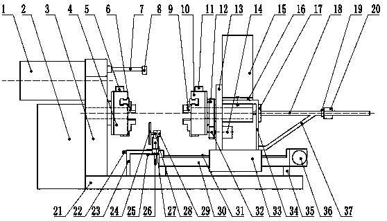
[0023] A multifunctional bolt and stud maintenance device, comprising at least a large base 21, characterized in that: a large bracket 3 is fixed on the left side of the large base 21, a motor-1 is fixed on the top of the large bracket 3, and the driving end of the motor-1 drives A left locking device is connected, and the left locking device is fixed on the right end face of the large bracket 3; the upper part of the large base 21 is fixed with a sliding mechanism through a plurality of supporting piles 35, the supporting mechanism is fixed above the sliding mechanism, and the motor 2 is fixed at the bottom of the supporting mechanism. 14. The driving end of motor two 14 is connected with a right locking device, and the right locking device is fixed on the left end surface of the supporting mechanism; the axes of the left locking device and the right locking device are on a straight line.

[0024] The invention solves the problems that nuts are difficult to be removed from bolts...

Embodiment 2

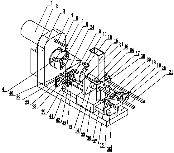
[0026] like figure 1 , figure 2 As shown, it is improved on the basis of Embodiment 1, and also includes a derusting device, which is fixed on the left side of the sliding mechanism and is located between the left locking device, the right locking device and the large base 21 .

[0027] Described derusting device comprises bottom support 23 at least, and bottom support 23 left ends are fixed on the big base 21, and bottom support 23 right ends are fixed on the slide mechanism, and bottom support 23 upper end surface is movably connected with slide block 43 that can move left and right, slide A horizontal driving motor 25 is fixed on the block one 43, and the driving end of the horizontal driving motor 25 is connected with a lead screw one 22. The left end surface of the bottom bracket 23 is fixed with a nut one 40, and the leading screw one 22 passes through the nut one 40 and extends to the bottom bracket. 23 outside; described slide block one 43 is also fixed with upper su...

Embodiment 3

[0031] like figure 1 , figure 2 As shown, it is improved on the basis of Embodiment 1 or Embodiment 2. The top of the right end surface of the large bracket 3 is fixed with a shooting rod 7, and the other end of the shooting rod 7 is fixed with a camera 8, and the camera 8 is located on the left locking device. , the top of the right locking device; the large bracket 3 is provided with a left connection through hole, the input shaft of the left locking device passes through the left connection through hole and is fixed with the large bracket 3, and the left end surface of the support mechanism is provided with The right connecting through hole, the input shaft of the right locking device passes through the right connecting through hole and is fixed with the supporting mechanism; the center lines of the left connecting through hole, the left locking device, the right locking device and the right connecting through hole are located at the same on a straight line.

[0032] Whe...


PUM


Abstract

The invention discloses a multifunctional bolt stud maintenance device. The maintenance device comprises a large base, wherein a large support is fixed on the left side of the large base, a motor I isfixed on the upper part of the large support, a driving end of the motor I is in transmission connection with a left locking device, and the left locking device is fixed on the right end face of thelarge support; a sliding mechanism is fixed on the upper part of the large base through a plurality of supporting piles, a supporting mechanism is fixed on the sliding mechanism, a motor II is fixed to the lower part of the supporting mechanism, a driving end of the motor II is in transmission connection with a right locking device, the right locking device is fixed on the left end face of the supporting mechanism, and the axes of the left locking device and the right locking device are located on a straight line; and the device further comprises a rust removal device which is fixed on the left side of the sliding mechanism and located on the lower right portion of the left locking device. According to the maintenance device, two three-jaw chuck is used for clamping a bolt and a stud so asto achieve the purpose of fixing and rotating, so that a nut can be detached under different working conditions, and the semi-automatic rust removal can be carried out the bolt, the stud and the nut;the maintenance device has the advantages of being reliable in performance, simple and convenient to operate, high in automation degree and high in efficiency.

Description

technical field [0001] The invention belongs to the technical field of maintenance devices, in particular to a multifunctional bolt and stud maintenance device. Background technique [0002] In daily production and life, a large number of bolts, studs, and nuts are used for mechanical connection, especially for industries such as oil exploration and development, transportation, processing and manufacturing, which have a large demand for studs and nuts. Exposure to air, soil, mud, aqueous solution and other media is not only easy to rust, but also difficult to disassemble the nuts from the bolts and studs. The disassembly work is not only labor-intensive, but also time-consuming, easy to fatigue, and easy to cause a large number of bolts , studs, and nuts are discarded; in addition, in order to ensure the recycling and reuse of high-value bolts, studs, and nuts, and achieve the goal of reducing costs and increasing efficiency, the recyclable bolts, studs, and nuts are mass-pr...

Claims


Application Information

Patent Timeline
Patent Type & Authority Applications(China)
IPC IPC(8): B23P19/06B24B27/033
CPCB23P19/06B24B27/033
Inventor 王思凡陈在君胡东锋李前春王玉赵航博张岄武自博段成才王玲
Owner BC P INC CHINA NAT PETROLEUM CORP
Why Eureka
Try Eureka