Long and thin rod-shaped electromagnet

A technology of electromagnets and slender rods, which is applied in the direction of electromagnets with armatures, electromagnets, engine components, etc., which can solve the problem of large electromagnets that cannot be installed in small spaces, increase engine fuel consumption and emissions, and fuel injection of fuel injectors. Problems such as slow response speed, to achieve the effect of rapid heat dissipation, increase service life, reduce fuel consumption and pollutant emissions

Pending Publication Date: 2020-08-11
成都威特电喷有限责任公司
View PDF2 Cites 0 Cited by
  • Summary
  • Abstract
  • Description
  • Claims
  • Application Information

AI Technical Summary

Problems solved by technology

[0004] In order to solve the problem that the electromagnet in the prior art has a large volume and cannot be installed in a narrow space. At the same time, it is far away from the nozzle of the fuel injector. After the solenoid valve is activated, the mechanical hydraulic delay is serious, and the response speed of the fuel injection of the fuel injector is slow, which is not conducive to the realization of fuel. Precise injection, increasing engine fuel consumption and emission problems

Method used


Image

  • Long and thin rod-shaped electromagnet
  • Long and thin rod-shaped electromagnet
  • Long and thin rod-shaped electromagnet

Examples


Embodiment 1

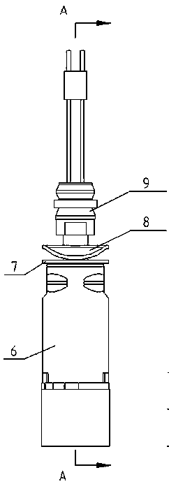
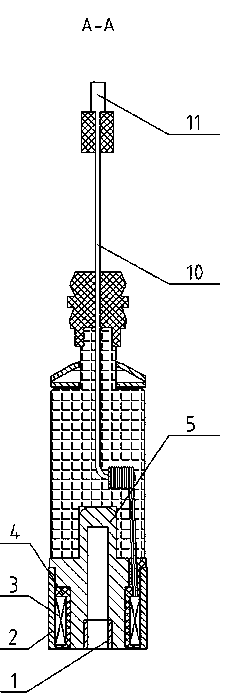
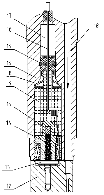
[0024] like figure 1 , figure 2 , image 3 As shown, the slender rod-shaped electromagnet described in this embodiment includes a magnetic isolation ring 1, an outer iron core 2, a coil 3, a bobbin 4, and an inner iron core 5, and is characterized in that: it also includes two terminal posts 10 ; The inner iron core 5 adopts an overall cylindrical stepped shaft shape and a stepped counterbore structure inside, the outer iron core 2 is fastened and installed on the stepped cylindrical surface of the inner iron core 5, and the outer cylindrical surface of the inner iron core 5 is connected to the outer cylindrical surface. The inner cylindrical surface of the iron core 2 is bonded; the coil 3 is installed on the outer cylindrical surface of the small end of the lower part of the inner iron core 5, and is wound on the coil frame 4 in a double-wire parallel winding manner, and is connected with the two terminals 10 The ends are fixed together; the magnetic isolation ring 1 is ...

Embodiment 2

[0029] On the basis of above-mentioned embodiment, propose embodiment 2, as figure 1 As shown, it is characterized in that: the slender rod-shaped electromagnet also includes a flat gasket 7 and a disc spring pad 8; the flat gasket 7 and the disc spring pad 8 are installed on the upper thin shaft of the plastic sealing post 6 part.

Embodiment 3

[0031] On the basis of above-mentioned embodiment, propose embodiment 3, as figure 2 As shown, it is characterized in that: the top of the coil 3 and the end face of the electromagnet are shallow and deep installation structures.

[0032] During implementation, the coil skeleton 4 at the top of the coil 3 is very thin, and the end of the coil 3 is very close to the end face of the electromagnet, so that a shallow and deep installation structure can be formed.

[0033] In this embodiment, the shallow and deep installation structure with the end of the coil 3 very close to the end face of the electromagnet can increase the electromagnetic force, further improve the response speed, and at the same time facilitate the rapid heat dissipation of the coil 3 and improve the service life of the electromagnet


PUM


Abstract

The invention provides a long and thin rod-shaped electromagnet. The long and thin rod-shaped electromagnet comprises a magnetic isolation ring (1), an outer iron core (2), a coil (3), a coil framework (4), an inner iron core (5) and a binding post (10), wherein the inner iron core (5) is in an integral cylindrical stepped shaft shape and is internally provided with a stepped counter bore structure, an outer cylindrical surface is attached to an inner cylindrical surface of the outer iron core (2), the coil (3) is installed on an outer cylindrical surface of a small end of a lower portion of the inner iron core (5) and fixedly connected with an end of the binding post (10), the magnetic isolation ring (1) is arranged at a lower part of the stepped counter bore of the inner iron core (5), and the inner iron core (5) is fixedly connected with the binding post (10) through a plastic sealing post (6). The electromagnet is advantaged in that a long and thin rod-shaped structure is adopted,the installation space is small, and problems that in the prior art, an electromagnet cannot be installed in a narrow space, the fuel injection response speed is low due to the fact that the electromagnet is away from a fuel injector nozzle, and accurate fuel injection is not facilitated are solved.

Description

technical field [0001] The invention relates to an elongated rod-shaped electromagnet, in particular to an elongated rod-shaped electromagnet in the technical field of engines. Background technique [0002] With the rapid development of social economy and the increasingly stringent national emission standards, the role of high-pressure common rail technology in the engine is becoming more and more important. In the diesel engine, the high-pressure fuel pumped by the high-pressure oil pump (the pressure exceeds 1000bar) is transported through the high-pressure oil pipe. to the high-pressure fuel rail, and then deliver the constant-pressure fuel stored in the high-pressure fuel rail to the electronically controlled fuel injector through the high-pressure fuel pipe, and send a current signal to the electromagnet on the electronically controlled fuel injector through the ECU controller, and the electromagnet is closed The armature causes the high-pressure fuel oil circuit to con...

Claims


Application Information

Patent Timeline
Patent Type & Authority Applications(China)
IPC IPC(8): H01F7/08F02M51/06
CPCF02M51/06H01F7/08
Inventor 桂理余波胡逍宇谢永华黄夫龙蔡林峰
Owner 成都威特电喷有限责任公司
Why Eureka
Try Eureka