Galvanic pile heat dissipation system and method for hydrogen energy automobile

A technology of a heat dissipation system and a heat dissipation method is applied in the field of the stack heat dissipation system of a hydrogen energy vehicle, and can solve the problems of unfavorable on-board fuel cell hydrogen use efficiency, low radiator efficiency, inability to solve and other problems.

Inactive Publication Date: 2020-08-11
祥博传热科技股份有限公司
View PDF5 Cites 6 Cited by
  • Summary
  • Abstract
  • Description
  • Claims
  • Application Information

AI Technical Summary

Problems solved by technology

The conventional use method is that the mixture of ordinary pure water and ethylene glycol conducts heat exchange with the fuel cell stack coolant through the wall of the radiator to reduce the fuel cell coolant to the required temperature range. The ef

Method used


Image

  • Galvanic pile heat dissipation system and method for hydrogen energy automobile
  • Galvanic pile heat dissipation system and method for hydrogen energy automobile
  • Galvanic pile heat dissipation system and method for hydrogen energy automobile

Examples


Embodiment 1

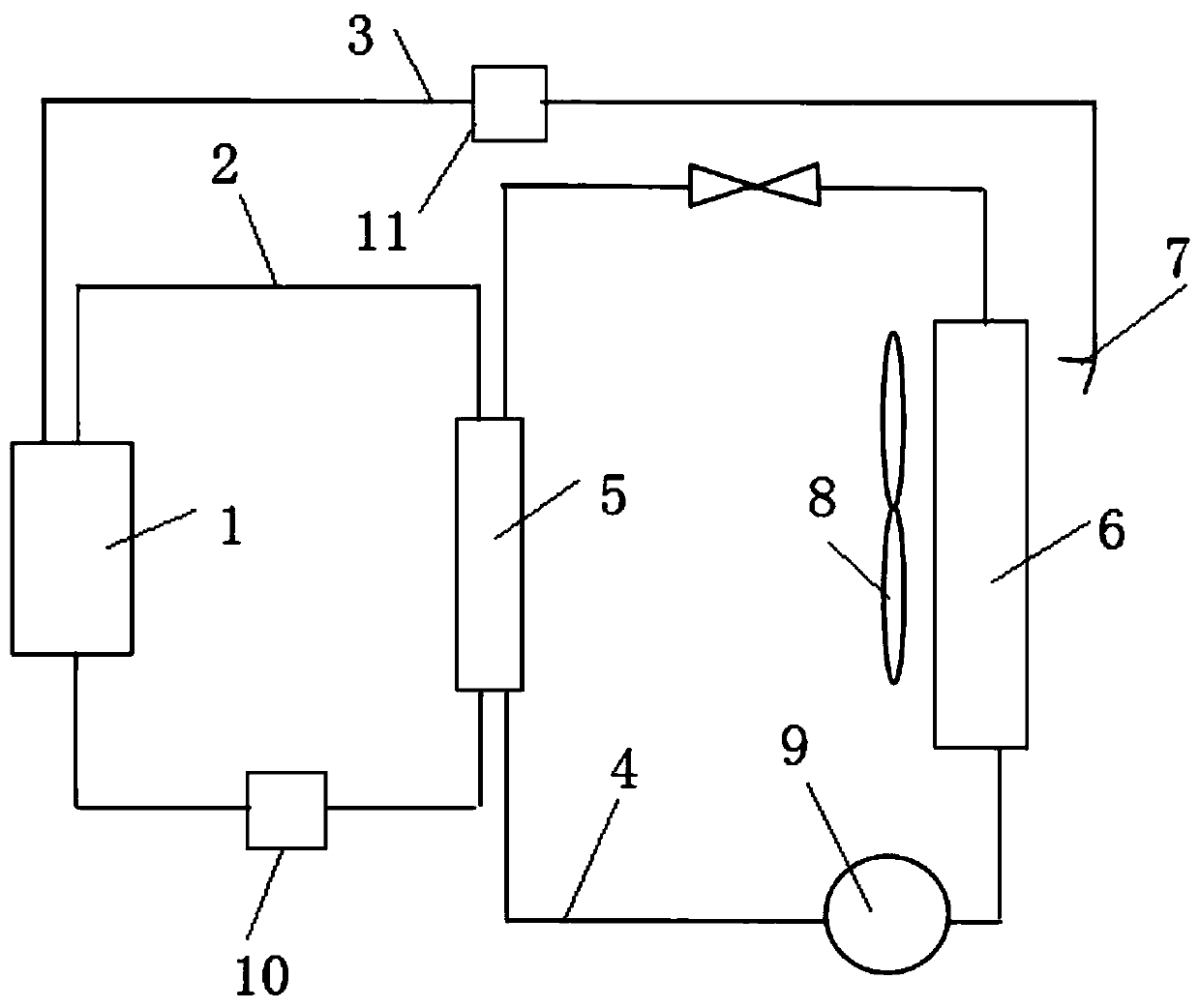
[0026] Example 1: See figure 1 As shown, the present invention is a stack heat dissipation system for a hydrogen energy vehicle, including a fuel cell 1 installed in the vehicle. The fuel cell 1 for the vehicle uses a heat exchange pipeline system and a heat dissipation pipeline when cooling down. system, wherein the heat dissipation pipeline system can be carried out by means of heat dissipation fan 8 and / or spray water cooling.

[0027] Specifically, the heat exchange pipeline system includes a liquid cooling pipeline 2 and a heat exchanger 5, wherein the liquid cooling pipeline 2 is equipped with a cooling night circulation pump 10 for cooling liquid in the liquid cooling pipeline 2, and the liquid cooling pipeline 2 is A closed-loop pipeline passing through the heat exchanger 5 and the fuel cell 1, wherein the heat exchanger 5 can be a plate heat exchanger;

[0028] When the cooling liquid transports the heat of the fuel cell 1 to the heat exchanger 5, the heat exchanger ...

Embodiment 2

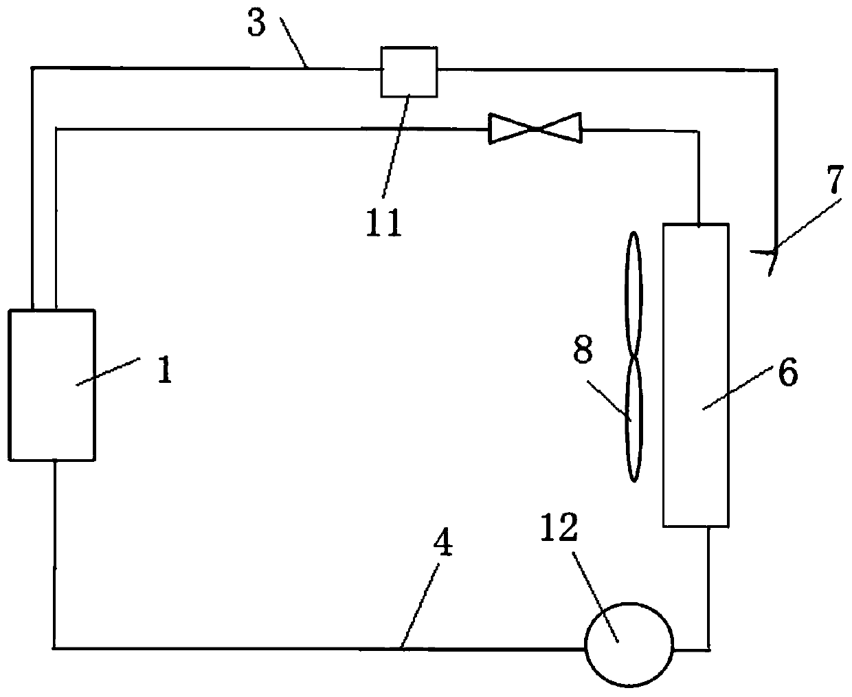
[0047] Other specific such as figure 2 As shown, this heat exchange method is to remove the heat exchange pipeline system in Embodiment 1, directly connect the refrigerant pipeline 4 on the heat dissipation pipeline system to the fuel cell 1, and remove the heat transfer device 9 and replace it with The circulation pump is used to dissipate heat from the fuel cell 1 . The water generated by the fuel cell is directly sprayed onto the radiator 6 and cooperates with the fan 8 to dissipate heat.


PUM


Abstract

The invention discloses a galvanic pile heat dissipation system and method for a hydrogen energy automobile, and belongs to the technical field. The system comprises a heat exchange system, a heat dissipation system and a spraying system, the heat exchange system comprises a liquid cooling pipeline passing through the fuel cell, and a heat exchanger and a heat transfer device through with the liquid cooling pipeline passes; the heat dissipation system comprises one of a compressor or a two-phase pump, a refrigerant pipeline and a radiator through which the refrigerant pipeline passes, a heat dissipation fan is arranged on the radiator, and the vaporization spraying system comprises a galvanic pile drainage collecting device, a spraying pipe and a spray head arranged at the output end of the spraying pipe. Water produced by reaction of the fuel cell is collected and sprayed to the radiator, so that the phase change evaporative cooling function is achieved, and the purpose of efficient heat dissipation is achieved. Meanwhile, the drained water is heated and vaporized by utilizing the heat of the radiator, so that the pavement can be effectively prevented from being slippery, the normal working range of the fuel cell is ensured, the electricity conversion efficiency of the fuel cell is improved, and the service life is prolonged.

Description

technical field [0001] The invention belongs to the technical field of electric stack heat dissipation, and in particular relates to an electric stack heat dissipation system and a method thereof for hydrogen energy vehicles. Background technique [0002] The hydrogen in the vehicle-mounted hydrogen fuel cell stack undergoes a chemical reaction with the oxygen in the air. In addition to electrical energy, a certain amount of heat energy is also generated. The heat will affect the performance of the fuel cell stack. Conventional radiators are used to cool the fuel cell stack coolant. The conventional use method is that the mixture of ordinary pure water and ethylene glycol conducts heat exchange with the fuel cell stack coolant through the wall of the radiator to reduce the fuel cell coolant to the required temperature range. The efficiency of conventional radiators is low, which is not conducive to on-board fuel The hydrogen usage efficiency of the battery cannot solve the p...

Claims


Application Information

Patent Timeline
IPC IPC(8): H01M8/04007H01M8/04029H01M8/04119B60L50/72B60L58/33
CPCB60L50/72B60L58/33H01M8/04007H01M8/04029H01M8/04067H01M8/04156Y02E60/50Y02T90/40
Inventor 夏波涛曾茂进季喜阳
Owner 祥博传热科技股份有限公司
Why Eureka
Try Eureka