Sludge discharge device and sludge discharge system for water treatment facility
A mud discharge device and water treatment technology, which is applied in the direction of distribution device, special distribution device, feeding/discharging device of settling tank, etc., can solve the problems of incomplete mud discharge and poor mud discharge effect, etc.
- Summary
- Abstract
- Description
- Claims
- Application Information
AI Technical Summary
Problems solved by technology
Method used
Image
Examples
Embodiment 1
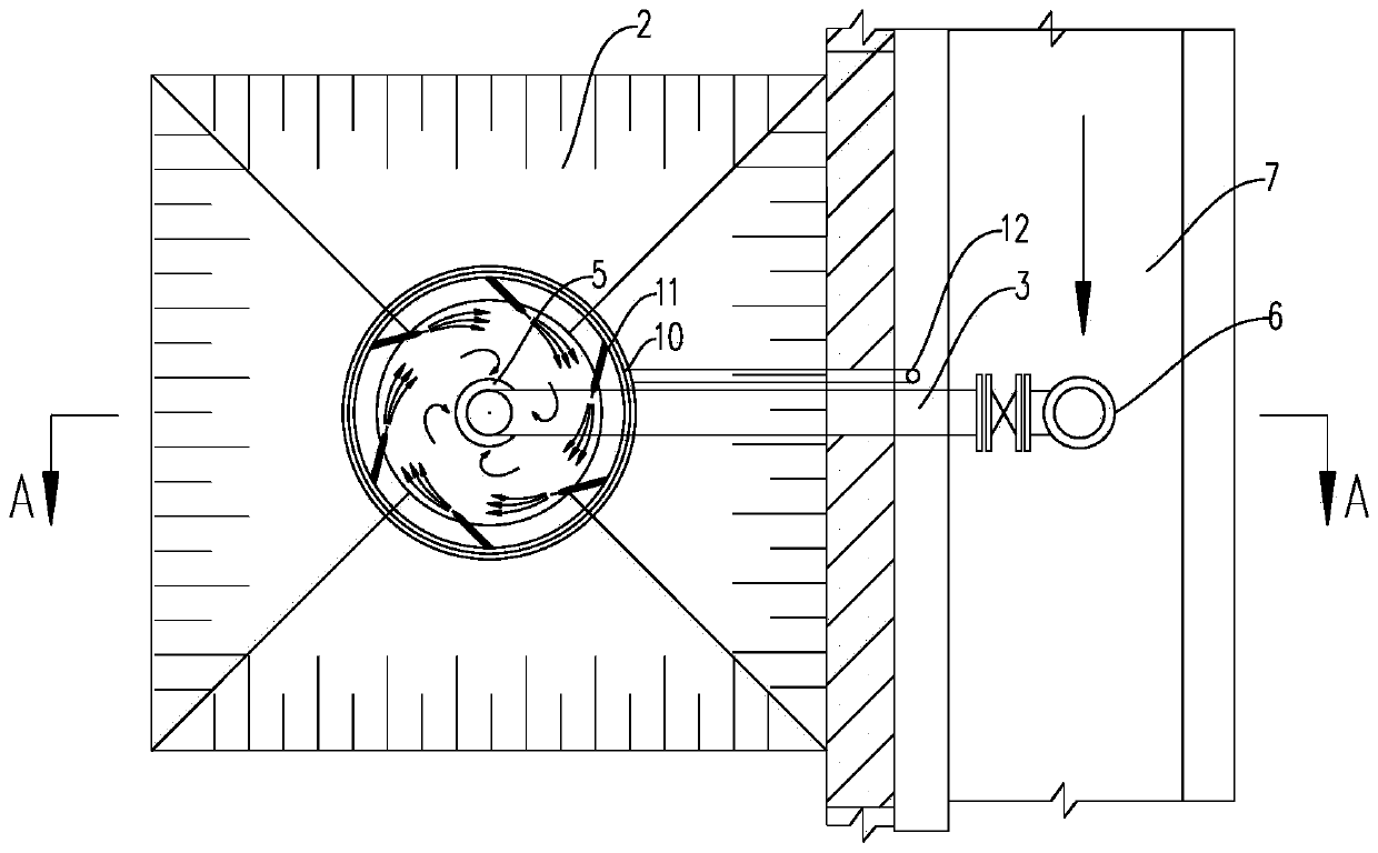
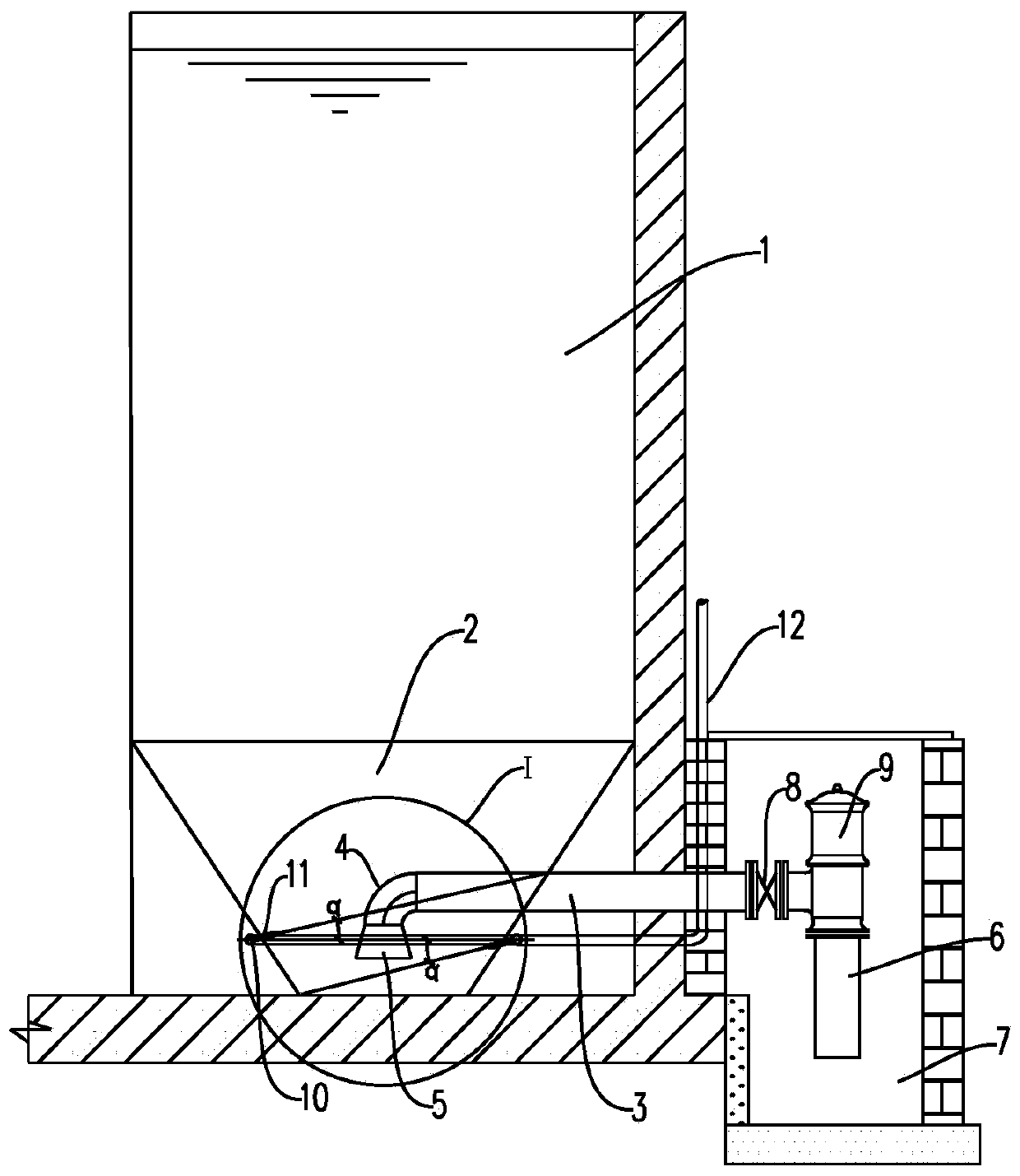
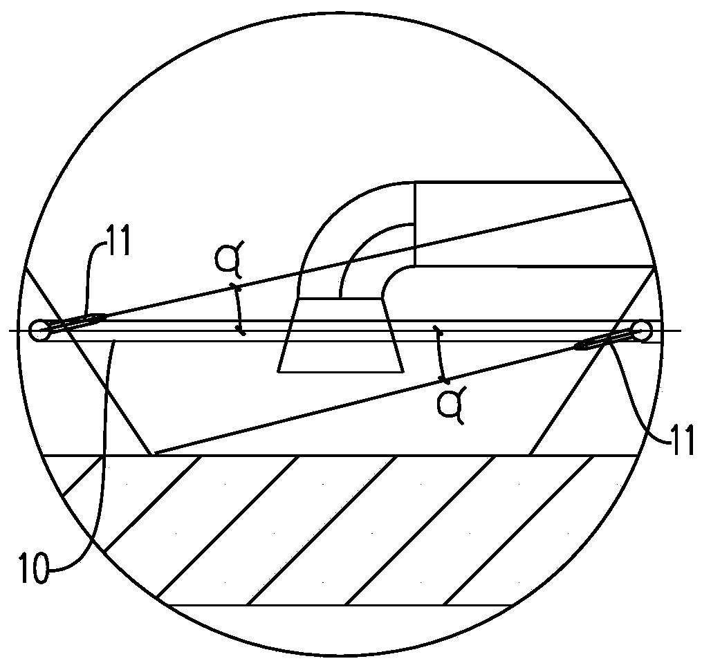
[0039] Such as figure 1 and 2 As shown, a sludge discharge device for a water treatment facility is arranged at the bottom of the water treatment tank, and includes a sludge discharge hopper 2 at the bottom of the water treatment tank 1, and a sludge discharge pipe 3 with one end extending into the sludge discharge hopper And a swirl injection mechanism for generating swirl water flow in the mud discharge pipe.
[0040] Such as figure 1 As shown, the mud discharge bucket 2 is a truncated conical structure with a square top (consistent with the cross-sectional shape and size of the water treatment tank) and a circular bottom. , wherein the inclination angle between the side wall of the mud discharge hopper 2 and the horizontal plane is preferably 45°-60°, which is beneficial for the precipitated particles in the water treatment tank to slide down to the bottom of the mud discharge hopper along the side wall of the mud discharge hopper.
[0041] The sludge discharge pipe 3 is...
Embodiment 2
[0055] In this embodiment, in order to obtain a better mud discharge treatment effect, the corresponding layout is made for the setting position of the water supply main pipe, the setting position of the trumpet and the setting position of the mud discharge pipe, as follows:
[0056] The distance between the large end opening of the horn 5 and the bottom surface of the mud discharge bucket 2 is 0.5D-D, preferably D. The setting position of the water supply main pipe 10 is higher than the position where the large end opening of the horn 5 is located, wherein the distance between the water supply main pipe 10 and the large end opening of the horn 5 is 0.5D-D, preferably 0.5D. The setting position of the mud discharge pipe 3 is higher than the location of the water supply pipe 10, wherein the distance between the central axis of the mud discharge pipe 3 and the bottom surface of the mud discharge bucket 2 is 2D-3D, preferably 2.8D.
[0057] At the same time, the height of the liq...
Embodiment 3
[0061] In the actual construction process of the mud discharge device, according to the size of the bottom surface of the water treatment tank, a single mud discharge hopper or multiple mud discharge hoppers can be arranged in parallel in the treatment tank, that is, one or more mud discharge hoppers are installed in the treatment tank A plurality of sludge discharge devices form the sludge discharge system of the water treatment facility.
[0062] When a mud discharge device is arranged at the bottom of the water treatment tank, the top of the mud discharge bucket is arranged in cooperation with the side wall of the water treatment tank.
[0063] When multiple sludge discharge devices are installed at the bottom of the water treatment tank, multiple sludge discharge hoppers are arranged side by side at the bottom of the water treatment tank in sequence, and between the sludge discharge hoppers, between the sludge discharge hopper and the side wall of the water treatment tank a...
PUM
 Abstract
Description
Claims
Application Information
 - R&D
- Intellectual Property
- Life Sciences
- Materials
- Tech Scout
- Unparalleled Data Quality
- Higher Quality Content
- 60% Fewer Hallucinations
Browse by: Latest US Patents, China's latest patents, Technical Efficacy Thesaurus, Application Domain, Technology Topic, Popular Technical Reports.
© 2025 PatSnap. All rights reserved.Legal|Privacy policy|Modern Slavery Act Transparency Statement|Sitemap|About US| Contact US: help@patsnap.com


