A kind of desiccant and its preparation system and preparation process
A preparation system and desiccant technology, applied in the direction of separation methods, dispersed particle separation, chemical instruments and methods, etc., can solve the problems of easy damage and difficult desiccant, and achieve the effect of not easy damage
- Summary
- Abstract
- Description
- Claims
- Application Information
AI Technical Summary
Problems solved by technology
Method used
Image
Examples
specific Embodiment approach 1
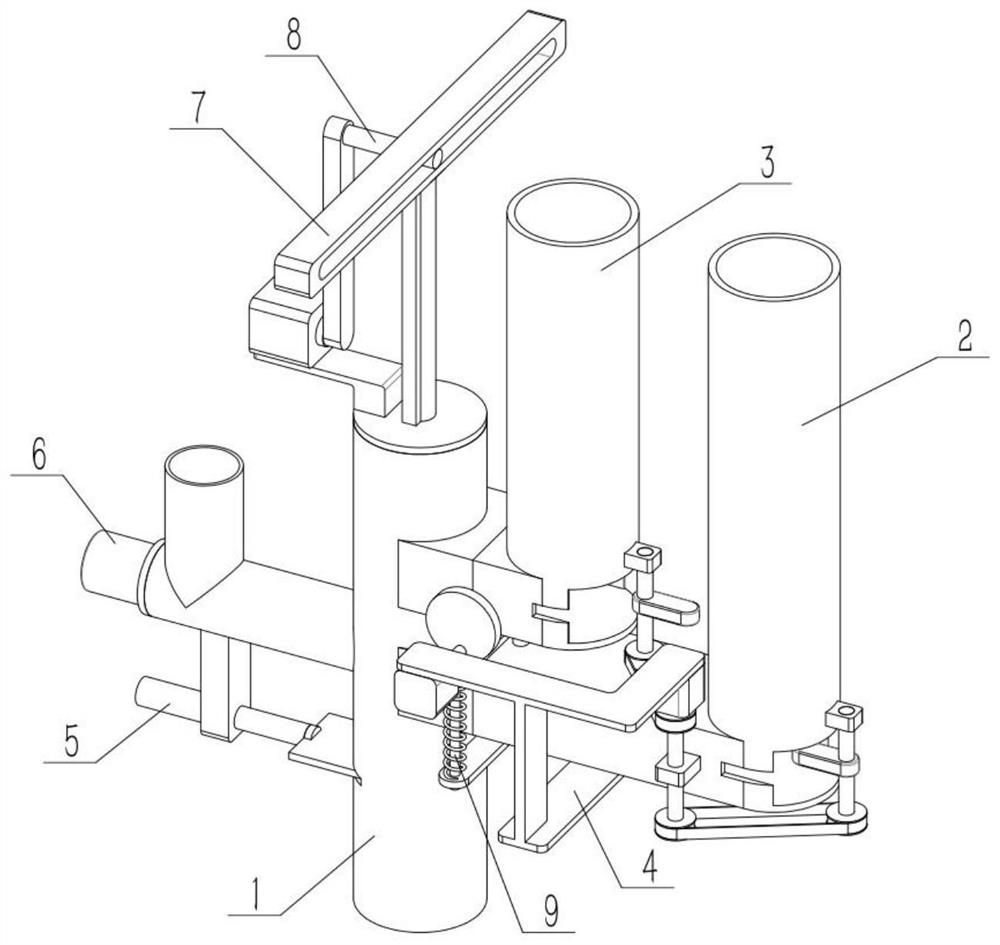
[0037] like Figure 1-12 As shown, a desiccant preparation system includes an interconnecting pipe 1, a bottom casing conveying pipe 2, a top casing conveying pipe 3, a double connection mechanism 4, a stop mechanism 5, a feeder 6, a shell buckle mechanism 7, and a start mechanism 8 And the perforation mechanism 9, the bottom shell conveying pipe 2 is fixed and communicated with the middle part of the right end of the interconnecting pipe 1, the top shell conveying pipe 3 is fixed and communicated with the upper side of the right end of the interconnecting pipe 1, and the double-connection mechanism 4 is conveyed with the bottom shell. The pipe 2 is connected, the stop mechanism 5 is slidably connected with the lower side of the intercommunication pipe 1, the stop mechanism 5 is fixed on the intercommunication pipe 1, the feeder 6 is fixed on the left end of the intercommunication pipe 1, and the buckle mechanism 7 is connected with the starting mechanism. 8 is connected, and ...
specific Embodiment approach 2
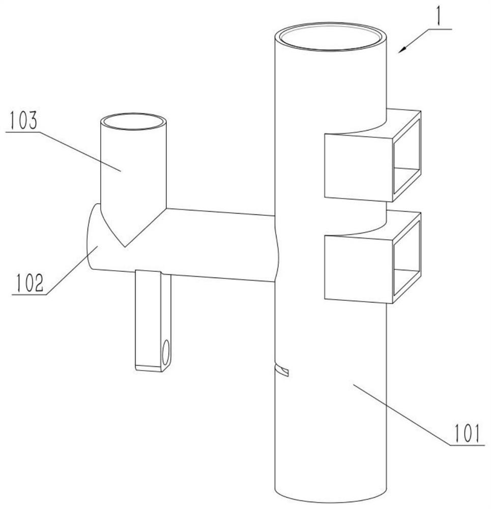
[0038] like Figure 1-12 As shown, the communication pipe 1 includes a main pipe 101, a feeding pipe 102 and a feeding pipe 103. The left end of the middle part of the main pipe 101 is fixedly connected to and communicated with the feeding pipe 102, and the upper end of the left side of the feeding pipe 102 is fixed and communicated with the feeding pipe 103. The desiccant particles are put into the feeding pipe 103 , and the movement of the desiccant particles in the feeding pipe 102 is controlled by the feeder 6 .
specific Embodiment approach 3
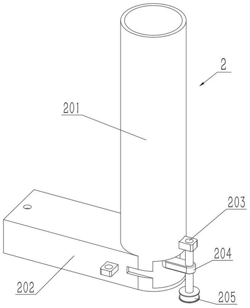
[0039] like Figure 1-12As shown, the bottom casing conveying pipe 2 includes a bottom casing straight pipe 201, a bottom casing flat pipe 202, a shaft I203, a lever 204 and a pulley I205, and the lower end of the bottom casing straight pipe 201 is fixedly connected and communicated with the bottom casing flat pipe 202 , the shaft I203 is rotatably connected to the lower side of the right end of the bottom casing straight pipe 201, the middle of the shaft I203 is fixed to the lever 204, the pulley I205 is fixed to the lower end of the shaft I203, and the left end of the bottom casing flat pipe 202 is fixed and connected to the main pipe The upper side of the right end of 101. The box body 10 is added to the bottom case straight pipe 201, the box body 10 is stacked in the bottom case straight pipe 201, and the rotating lever 204 is used to move the lowermost box body 10 to the left. After moving to the left, the upper box body 10 falls down and waits for the push of the lever ...
PUM
 Abstract
Description
Claims
Application Information
 - R&D
- Intellectual Property
- Life Sciences
- Materials
- Tech Scout
- Unparalleled Data Quality
- Higher Quality Content
- 60% Fewer Hallucinations
Browse by: Latest US Patents, China's latest patents, Technical Efficacy Thesaurus, Application Domain, Technology Topic, Popular Technical Reports.
© 2025 PatSnap. All rights reserved.Legal|Privacy policy|Modern Slavery Act Transparency Statement|Sitemap|About US| Contact US: help@patsnap.com


