Particle dissolving and stirring part

A technology for stirring parts and particles, applied in the field of particle dissolving stirring parts, can solve the problems of prolonged stirring period, different dissolving speed, low stirring efficiency, etc., and achieve the effect of improving stirring efficiency and improving the effect of turbulence.

Pending Publication Date: 2020-08-14
万强
View PDF7 Cites 7 Cited by
  • Summary
  • Abstract
  • Description
  • Claims
  • Application Information

AI Technical Summary

Problems solved by technology

[0002] The traditional agitator is usually composed of a variable frequency motor, a stirring shaft and a stirring rod fixed at the output end of the variable frequency motor, and is used to dissolve solid particles in the stock solution. The particle dissolution rate is different, which indirectly prolongs the stirring cycle, and does not have the crushing effect, which further requires a longer stirring cycle to gradually dissolve, and the stirring efficiency is low

Method used


Image

  • Particle dissolving and stirring part

Examples


Embodiment

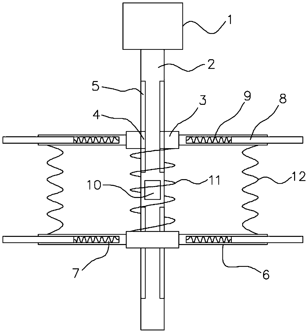
[0016] refer to figure 1 , a particle dissolving stirrer, comprising a variable frequency motor 1, the output end of the variable frequency motor 1 is fixedly connected with a stirring shaft 2, the stirring shaft 2 is embedded with an electromagnetic block 10, and the electromagnetic block 10 is connected to an external DC power supply through a rheostat, The direction of the magnetic field generated by the electromagnetic block 10 is fixed, and two permanent magnet rings 3 are sheathed symmetrically with respect to the electromagnetic block 10 on the stirring shaft 2, and the electromagnetic block 10 is arranged to repel each other with the two permanent magnet rings 3 respectively, and the two permanent magnet rings 3 The suction is set, the inside of the permanent magnet ring 3 is symmetrically provided with a limit mechanism, the stirring shaft 2 is sleeved with a second spring 11, and the two ends of the second spring 11 are fixedly connected with the two permanent magnet ...


PUM


Abstract

The invention discloses a particle dissolving and stirring part. The particle dissolving and stirring part comprises a variable frequency motor, an output end of the variable frequency motor is fixedly connected with a stirring shaft, an electromagnetic block is embedded in a stirring shaft, two permanent magnet rings are symmetrically arranged on the stirring shaft relative to the electromagneticblock in a sleeving manner, the electromagnetic block and the two permanent magnet rings are arranged in a repulsion manner, the two permanent magnet rings are arranged in an attracting manner, limiting mechanisms are symmetrically arranged on the inner sides of the permanent magnet rings, the stirring shaft is sleeved with a second spring, the two ends of the second spring are fixedly connectedwith the two permanent magnet rings correspondingly, a plurality of main stirring rods are fixedly connected to the outer circumferential faces of the permanent magnet rings in the circumferential direction, and square telescopic grooves are formed in the ends, away from the permanent magnet rings, of the main stirring rods. The main stirring rods and the auxiliary stirring rods form a whole stirring body, the length of the whole stirring body and the position of the whole stirring body relative to the stirring shaft are changed, the dissolving efficiency is greatly improved, solid particles are crushed through the telescopic springs, and the stirring efficiency is improved.

Description

technical field [0001] The invention relates to the technical field of stirring and dissolving, in particular to a particle dissolving stirring piece. Background technique [0002] The traditional agitator is usually composed of a variable frequency motor, a stirring shaft and a stirring rod fixed at the output end of the variable frequency motor, and is used to dissolve solid particles in the stock solution. The dissolving speed of the particles is different, which indirectly prolongs the stirring cycle, and does not have the crushing effect, which further requires a longer stirring cycle to gradually dissolve, and the stirring efficiency is low. [0003] In order to solve the above problems, we propose a particle dissolving stirring piece. Contents of the invention [0004] The purpose of the present invention is to solve the problems in the background technology, and propose a particle dissolving stirring piece. [0005] In order to achieve the above object, the prese...

Claims


Application Information

Patent Timeline
Patent Type & Authority Applications(China)
IPC IPC(8): B01F1/00B01F13/10
CPCB01F21/10B01F33/8305B01F33/83612
Inventor 万强
Owner 万强
Why Eureka
Try Eureka