Rebar smelting extrusion molding machine

An extrusion molding machine and smelting technology, which is applied to casting molding equipment, casting molds, cores, etc., can solve problems such as quality impact and steel bar product quality, and achieve stable and powerful functions, improve injection molding efficiency, and sensitive work. Effect

Inactive Publication Date: 2020-08-14
新昌县七星街道盈捷机械厂
View PDF0 Cites 1 Cited by
  • Summary
  • Abstract
  • Description
  • Claims
  • Application Information

AI Technical Summary

Problems solved by technology

[0002] The work of smelting and forming steel bars in the prior art involves injection molding of high-temperature molten iron. After one end of the molten iron is squeezed and injected for a period of time, the molten iron cools still in the forming cavity to realize the work of forming steel bars. Similar to the injection molding mechanism, the molten iron is drawn from the forming pipe. Injection at one end, when the molten iron completely flows to the other end of the forming pipe, there will inevitably be a temperature change during this process, which will affect the quality of the steel product, because the steel molten iron flows in the forming pipe, the temperature of the molten iron that first flows into the forming pipe The more the drop, the temperature of the molten iron in the final forming pipe is not exactly the same, such a slight difference will have a certain impact on the quality of the steel bar after forming, so we provide a steel bar smelting extrusion molding machine

Method used


Image

  • Rebar smelting extrusion molding machine
  • Rebar smelting extrusion molding machine
  • Rebar smelting extrusion molding machine

Examples


Embodiment Construction

[0018] The following will clearly and completely describe the technical solutions in the embodiments of the present invention with reference to the accompanying drawings in the embodiments of the present invention. Obviously, the described embodiments are only some, not all, embodiments of the present invention. Based on the technical solutions in the present invention, all other embodiments obtained by persons of ordinary skill in the art without making creative efforts belong to the protection scope of the present invention.

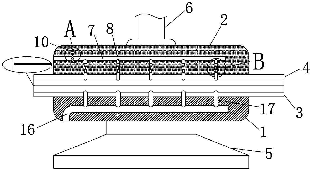
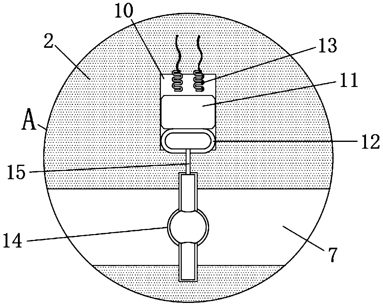
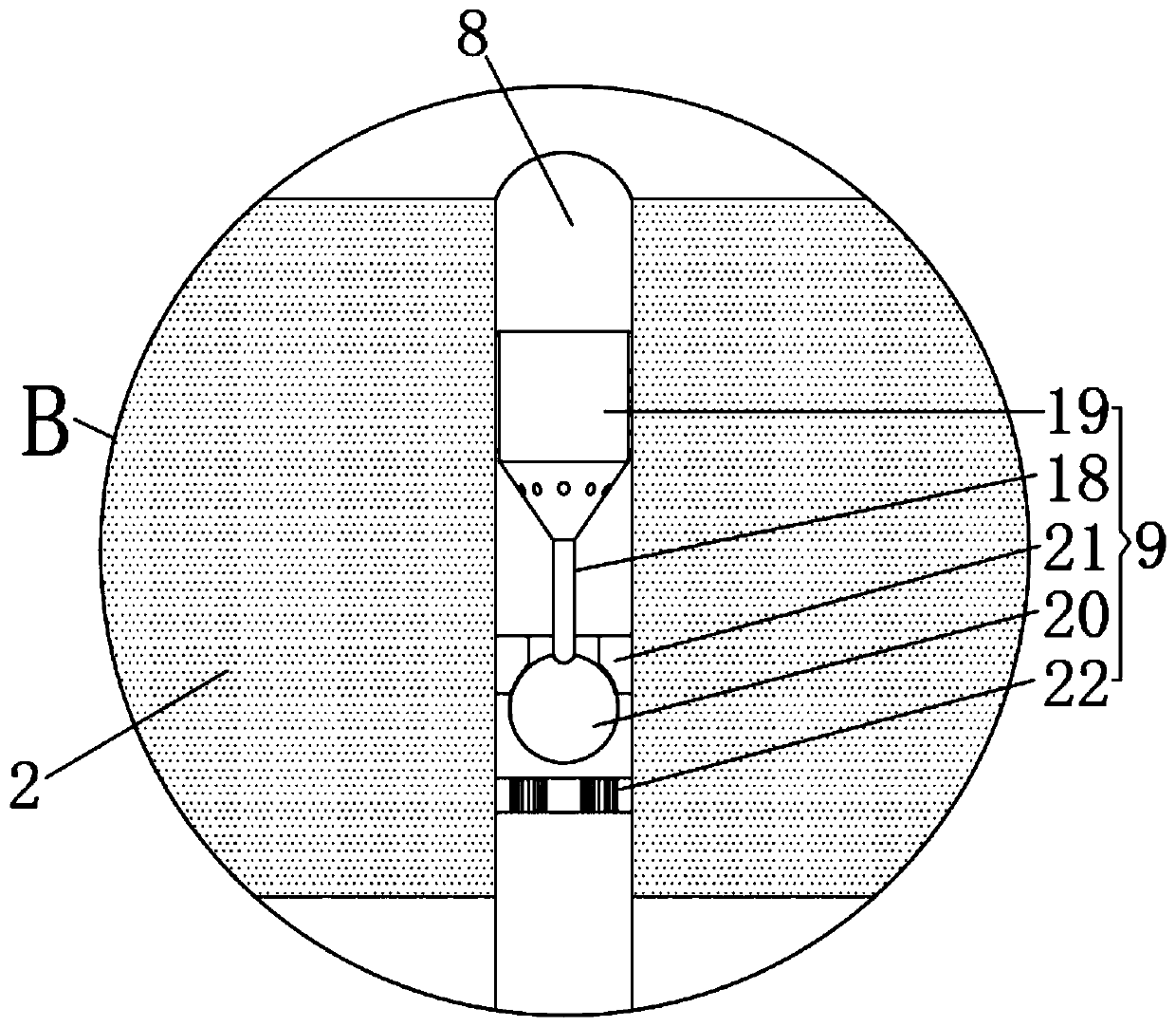
[0019] see Figure 1 to Figure 4 , the present invention provides a technical solution: a steel bar smelting extrusion molding machine, comprising a lower plate 1, an upper plate 2, a lower half pipe 3 and an upper half pipe 4, the upper end of the lower plate 1 is fixedly embedded with a lower half pipe 3, The lower end of the lower plate 1 is fixedly connected with the base 5, the lower end of the upper plate 2 is fixedly embedded with the upper half...


PUM


Abstract

The invention relates to the technical field of rebar molding, in particular to a rebar smelting extrusion molding machine. The rebar smelting extrusion molding machine comprises a lower plate, an upper plate, a lower half pipe and an upper half pipe, wherein the lower half pipe is fixedly embedded in the upper end of the lower plate, a base is fixedly connected to the lower end of the lower plate, the upper half pipe is fixedly embedded in the lower end of the upper plate, a lifting column is fixedly connected to the upper end of the upper plate, the lower half pipe and the upper half pipe have the same shape of a half cylinder and are connected into a cylinder shape in a butt joint manner, an air pipe cavity and branch pipe cavities are formed in the upper plate, and one side of the airpipe cavity communicates with the several evenly-distributed branch pipe cavities. By means of the rebar smelting extrusion molding machine, the molten iron injection molding work can be performed inthe several unit pipe cavities at the same time, a traditional mode of injecting molten iron from one end of a molding pipeline is replaced, and the efficiency of molten iron injection molding and thequality of rebars are greatly improved; and through the design of a heat conductor, whether airflow passes through the air pipe cavity or not is sensitively sensed, then the progress of the molten iron extrusion injection molding work is fed back, and the function is stable and powerful.

Description

technical field [0001] The invention relates to the technical field of steel bar forming, in particular to a steel bar smelting extrusion molding machine. Background technique [0002] The work of smelting and forming steel bars in the prior art involves injection molding of high-temperature molten iron. After one end of the molten iron is squeezed and injected for a period of time, the molten iron cools still in the forming cavity to realize the work of forming steel bars. Similar to the injection molding mechanism, the molten iron is drawn from the forming pipe. Injection at one end, when the molten iron completely flows to the other end of the forming pipe, there will inevitably be a temperature change during this process, which will affect the quality of the steel product, because the steel molten iron flows in the forming pipe, the temperature of the molten iron that first flows into the forming pipe The more the drop, the temperature of the molten iron in the final for...

Claims


Application Information

Patent Timeline
Patent Type & Authority Applications(China)
IPC IPC(8): B22D37/00B22C9/22B22C9/08
CPCB22C9/082B22C9/22B22D37/00
Inventor 屈珠丽
Owner 新昌县七星街道盈捷机械厂
Why Eureka
Try Eureka