PPR pipefitting uniform cutting device

A cutting equipment and uniform technology, applied in the field of uniform cutting equipment for PPR pipe fittings, can solve the problems of manpower consumption and low work efficiency, and achieve the effects of saving time, improving work efficiency and simple operation

Active Publication Date: 2020-08-14
马云艳
View PDF7 Cites 4 Cited by
  • Summary
  • Abstract
  • Description
  • Claims
  • Application Information

AI Technical Summary

Problems solved by technology

[0004] In order to overcome the shortcomings of the above-mentioned method, which requires manual hand-held PPR pipes to be cut all the time during operation, which is more manpower-intensive, and requires repeated comparisons during cutting, and the shor

Method used


Image

  • PPR pipefitting uniform cutting device
  • PPR pipefitting uniform cutting device
  • PPR pipefitting uniform cutting device

Examples


Example Embodiment

[0021] Example 1

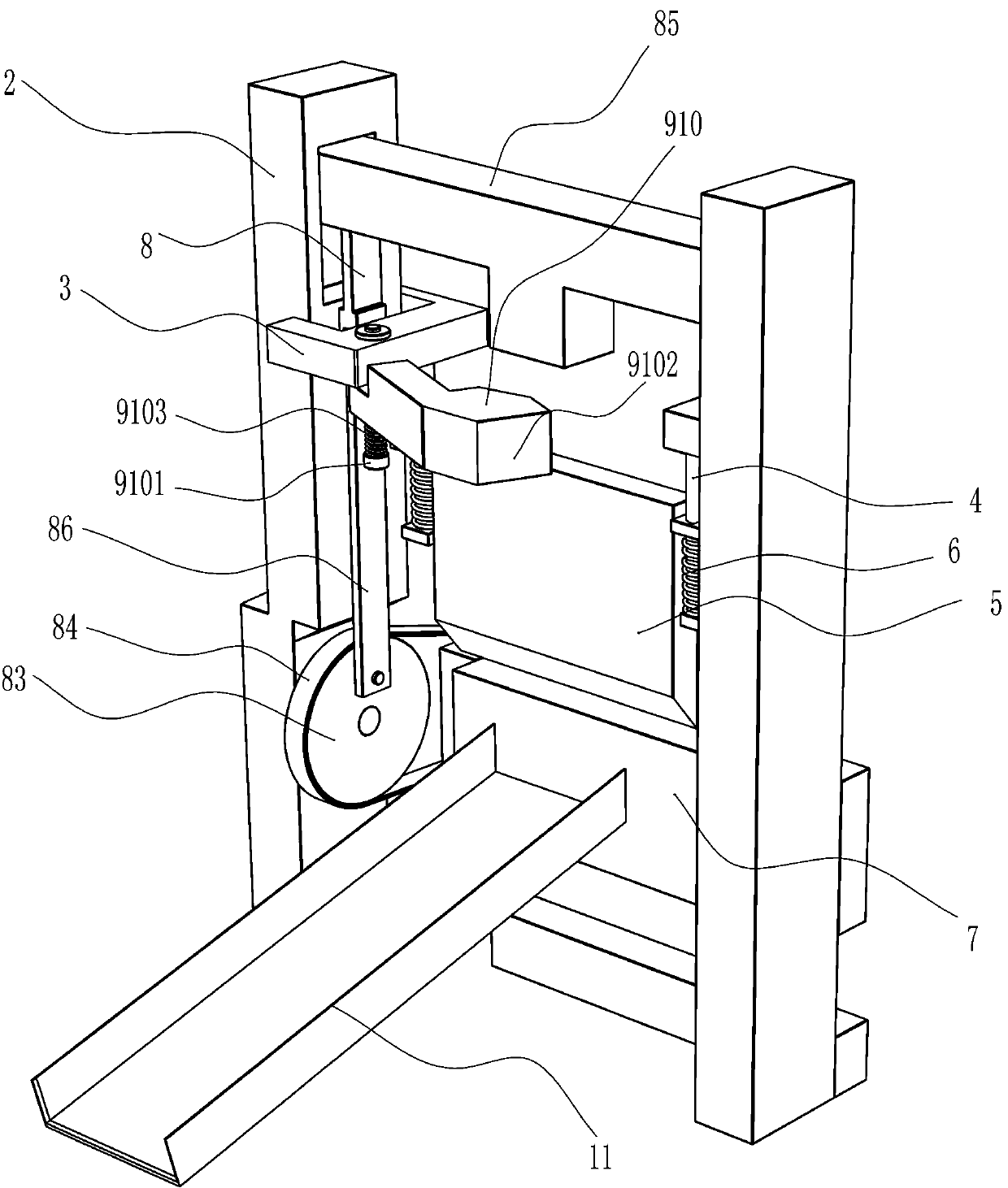
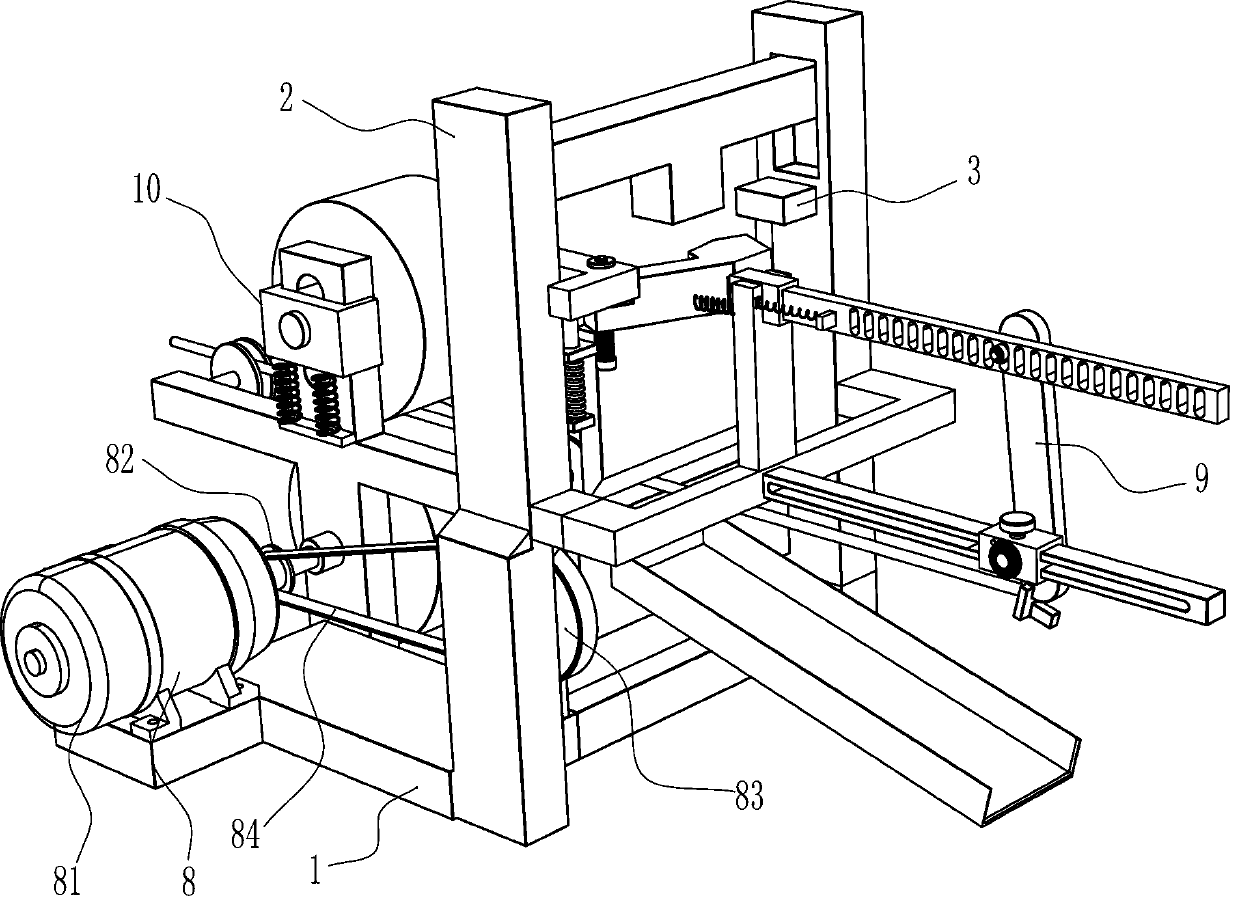
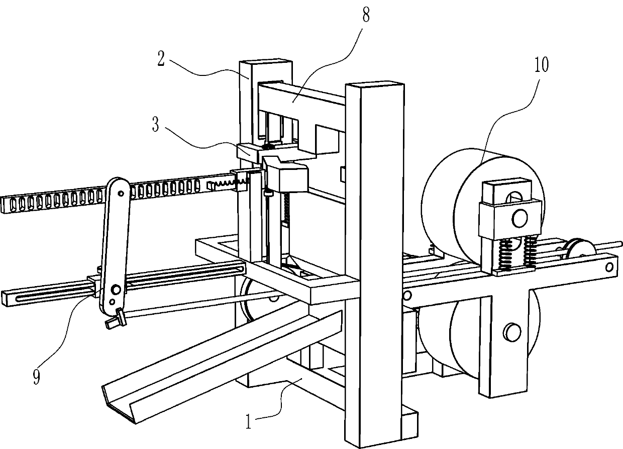
[0022] A uniform cutting equipment for PPR pipe fittings, such as Figure 1-4 As shown, it includes a base 1, a rack 2, a fixed block 3, and a guide rod 4. The base 1 is connected with a rack 2. The upper left and right sides of the rack 2 are connected with fixed blocks 3, and the bottom of the fixed block 3 is connected The guide rod 4 also includes a cutting knife 5, a first return spring 6, a knife seat 7, a power mechanism 8 and a distance mechanism 9. The cutting knife 5 is slidably connected between the guide rods 4 on both sides, the cutting knife 5 and the guide A first return spring 6 is connected between the rods 4, a knife holder 7 is connected to the lower part of the frame 2, and the knife holder 7 is located under the cutter 5, and a power mechanism 8 and a distance mechanism 9 are provided between the base 1 and the frame 2. .

[0023] The power mechanism 8 includes a geared motor 81, a small pulley 82, a large pulley 83, a flat belt 84, a T-sha...

Example Embodiment

[0027] Example 2

[0028] On the basis of Example 1, such as Figure 5 As shown, it also includes a feeding assembly 10. The feeding assembly 10 includes a cross 101, a lower feeding roller 102, a guide wheel 103, a sliding seat 104, an upper feeding roller 105 and a tension spring 106. The left and right sides of the top rear side of the base 1 Both crosses 101 are connected, and the lower feed roller 102 is rotatably connected between the lower parts of the crosses 101 on both sides. The output shaft of the reduction motor 81 is connected with the drive shaft of the lower feed roller 102. The upper part of the cross 101 on both sides is slidably connected with a sliding seat 104, the upper feeding roller 105 is rotatably connected between the sliding seats 104 on both sides, and a tension spring is connected between the sliding seat 104 and the cross 101. 106.

[0029] When placing the PPR pipe fittings, the PPR pipe fittings can be placed on the knife holder 7 through the two g...


PUM


Abstract

The invention relates to cutting equipment, in particular to a PPR pipefitting uniform cutting device. The PPR pipefitting uniform cutting device is easy to operate, capable of effectively saving manpower, capable of saving consumed time during work, and capable of improving the work efficiency. The PPR pipefitting uniform cutting device comprises a base, a cutter and a cutter holder, a rack is connected to the base, fixed blocks are connected to the upper portions of the two sides of the rack, the bottoms of the fixed blocks are connected with guide rods, the cutter is in sliding connection to the position between the guide rods on the two sides, first reset springs are connected between the cutter and the guide rods, the cutter holder is connected to the lower portion in the rack, and the cutter holder is located below the cutter. Through a power mechanism, the cutter is driven to cut a PPR pipeline, and the effect of cutting the PPR pipeline is achieved.

Description

Technical field [0001] The invention relates to a cutting device, in particular to a uniform cutting device for PPR pipe fittings. Background technique [0002] PPR pipe is an updated product of UPVC water supply pipe, aluminum plastic pipe, PE-X pipe and PE-RT pipe. Because it uses random copolymerization technology, the strength and high temperature resistance of polypropylene are well guaranteed, thus becoming The main force of water pipe materials, after the PPR pipe is manufactured, in order to facilitate the transportation of the pipe, a long PPR pipe is usually cut into multiple PPR pipes of uniform length. [0003] At present, the method of uniformly cutting PPR pipes is usually to cut a PPR pipe first, then compare the cut PPR pipe with the uncut part, and then cut a PPR pipe with the same length. The above method is in operation At times, it is necessary to manually hold the PPR pipe for cutting, which is more labor-intensive, and requires repeated comparisons during cut...

Claims


Application Information

Patent Timeline
IPC IPC(8): B26D1/08B26D5/08B26D7/01B26D7/28B26D7/06
CPCB26D1/08B26D5/086B26D7/01B26D7/28B26D7/06B26D2007/013
Inventor 马云艳
Owner 马云艳
Why Eureka
Try Eureka