Assembling device for packaging box
A technology for assembling devices and packaging boxes, which is applied in the direction of packaging, etc. It can solve the problems of unfavorable batch work, inability to assist in the expansion of packaging boxes, and the need for loading personnel to spend more manpower, so as to improve efficiency and reduce the steps of manual expansion.
- Summary
- Abstract
- Description
- Claims
- Application Information
AI Technical Summary
Problems solved by technology
Method used
Image
Examples
no. 1 example
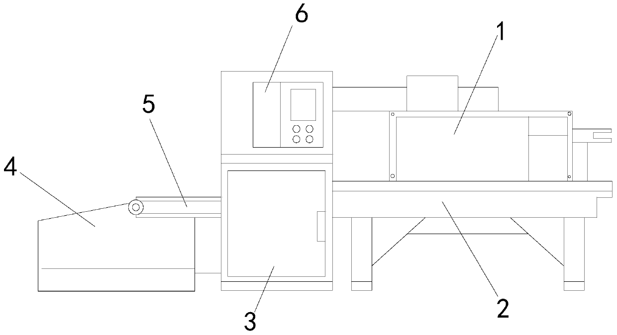
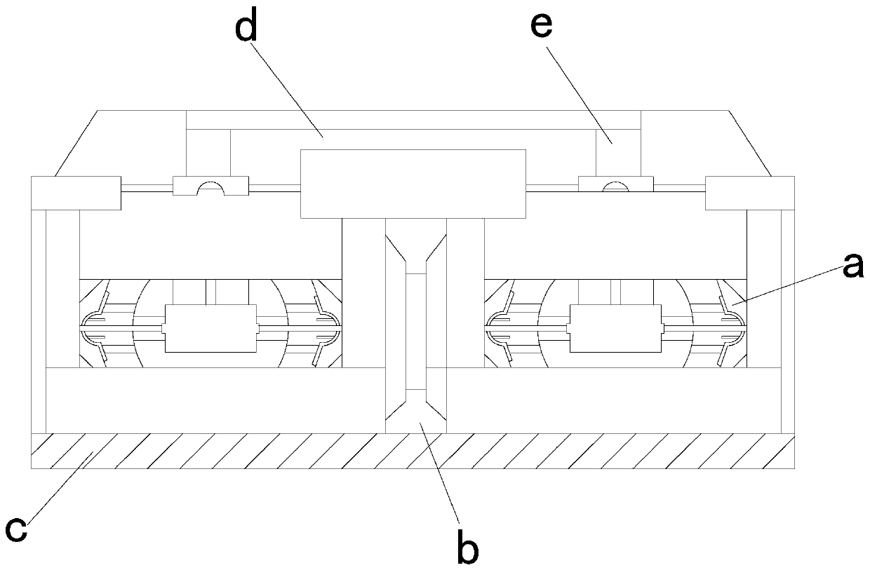
[0025] see Figure 1-Figure 3 , the present invention provides a technical solution for an assembly device of a packaging box: its structure includes: a self-expandable body 1, a base 2, a motor cabinet 3, a collection bin 4, a conductive belt 5, and a control cabinet 6, and the collection bin 4 is installed on a conductive The left side of the belt 5 is buckled with the conduction belt 5, the right side of the conduction belt 5 is provided with a motor cabinet 3, and a control cabinet 6 is provided above the motor cabinet 3, and the control cabinet 6 is electrically connected with the motor cabinet 3. The right side of the conduction belt 5 is provided with a self-deployable body 1, the self-deployment body 1 is movably connected with the conduction belt 5, a base 2 is provided under the self-deployment body 1, and the base 2 is locked with the self-deployment body 1, The self-expanding body 1 includes a matching frame device a, a partition plate b, an installation box c, a p...
no. 2 example
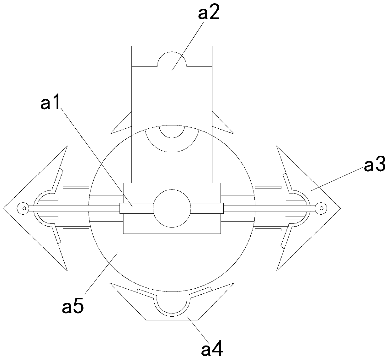
[0029] see Figure 4-Figure 5 , the present invention provides a technical solution for an assembly device of a packaging box: its structure includes: the adjustment device a1 includes a cable a11, a limit ring a12, a movable rod group a13, an angle plate a14, a sleeve a15, and a pressure plate a16. The cable a11 is installed at the end of the sleeve a15 and fastened with the sleeve a15, the top of the sleeve a15 is provided with an angle plate a14, the angle plate a14 is movably connected with the sleeve a15, and the upper end of the angle plate a14 is provided with Movable rod group a13, the movable rod group a13 is fastened to the angle plate a14, a limit ring a12 is provided between the sleeves a15, the limit ring a12 is fastened to the sleeve a15, and the limit ring a12 A pressing plate a16 is arranged below, and the pressing plate a16 is welded to the limiting ring a12.
[0030] The splint device a3 includes a sliding piece a31, a telescopic frame a32, a clip set a33, a...
PUM
 Abstract
Description
Claims
Application Information
 - R&D
- Intellectual Property
- Life Sciences
- Materials
- Tech Scout
- Unparalleled Data Quality
- Higher Quality Content
- 60% Fewer Hallucinations
Browse by: Latest US Patents, China's latest patents, Technical Efficacy Thesaurus, Application Domain, Technology Topic, Popular Technical Reports.
© 2025 PatSnap. All rights reserved.Legal|Privacy policy|Modern Slavery Act Transparency Statement|Sitemap|About US| Contact US: help@patsnap.com


