Packaging Structure and Packaging Technology of Lead Frame

A lead frame and packaging structure technology, which is applied to cleaning methods, cleaning methods and utensils using tools, static electricity, etc., can solve the problems of cumbersome, poor heat dissipation, affecting the stability of chip connection points, etc., to achieve heat dissipation and avoid adsorption. The effect of dust and convenient packaging

Active Publication Date: 2022-06-07
NINGBO DEZHOU PRECISION ELECTRONIC CO LTD
View PDF0 Cites 0 Cited by
  • Summary
  • Abstract
  • Description
  • Claims
  • Application Information

AI Technical Summary

Problems solved by technology

[0003] Nowadays, in the process of encapsulating the lead frame, it often needs to be sealed by the shell to provide protection for the lead frame and the chips on it. The shell used for external encapsulation is generally composed of an upper shell and a lower shell. In this case, the user needs to fix the connection points of the upper shell and the lower shell in turn through multiple bolts, which is relatively cumbersome, and the traditional packaging structure generally only provides heat dissipation ports on the shell for heat dissipation, and the heat dissipation effect is poor. In addition, due to The chip is fixed on the lead frame by glue, which makes the glue easy to be thermally expanded to generate stress, which affects the stability of the chip connection point

Method used


Image

  • Packaging Structure and Packaging Technology of Lead Frame
  • Packaging Structure and Packaging Technology of Lead Frame
  • Packaging Structure and Packaging Technology of Lead Frame

Examples


Embodiment Construction

[0026] The following embodiments are for illustrative purposes only and are not intended to limit the scope of the present invention.

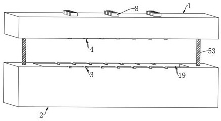
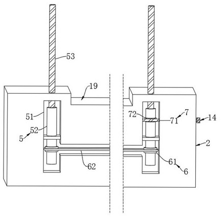
[0027] as Figure 1-6As shown, a lead frame package structure, comprising the upper cover 1 and the lower cover 2, the lower cover 2 is opened with a placement slot 19, and both sides of the lower cover 2 are opened with a plurality of pin slots 3 in line with the placement slot 19, the upper cover 1 is fixedly connected with the pin slot 3 with the briquette 4, the lower cover 2 is provided with two lifting mechanisms 5, and the output end of the two lifting mechanism 5 are fixedly connected with the upper cover 1, the lifting mechanism 5 is composed of a cavity 51, a nut seat 52 and a screw 53, The cavity 51 is opened on the lower seat 2, and the rotation of the nut seat 52 is provided in the cavity 51, the screw 53 is connected with the thread of the nut seat 52 thread, and the upper end of the screw 53 runs through the cavity 51 and is fixedly ...


PUM


Abstract

The invention belongs to the technical field of lead frame packaging structure, and in particular relates to the packaging structure of the lead frame and its packaging process, including an upper cover and a lower sealing seat, the lower sealing seat is provided with a placement groove, and the two sides of the lower sealing seat are There are a plurality of pin slots matching with the placement slots, the upper cover is fixedly connected with a pressing block matching with the pin slots, and the lower cover is provided with two lifting mechanisms, and two The output ends of the lifting mechanisms are all fixedly connected to the upper cover, and a linkage mechanism is arranged between the two lifting mechanisms. The invention can greatly optimize the packaging link, and at the same time, it can effectively buffer the impact stress on the chip on the lead frame during the packaging and use process, and the invention can effectively utilize waste energy to assist in improving the heat dissipation inside the packaging structure during the working process At the same time, it can effectively remove the dust on the dust-proof net, and can eliminate the static electricity on the bristles to prevent the bristles from absorbing dust.

Description

Technical field [0001] The present invention belongs to the field of lead frame packaging structure technology, in particular with respect to the packaging structure of the lead frame and its packaging process. Background [0002] As the chip carrier of an integrated circuit, the lead frame is a key structural component that realizes the electrical connection between the lead end of the internal circuit of the chip and the external lead with the help of bonding materials to form an electrical circuit. It plays a role as a bridge to connect with external wires, and most of the semiconductor modules need to use lead frames, which is an important basic material in the electronic information industry. [0003] Nowadays, the lead frame in the process of packaging, often need to be sealed through the housing, in order to provide protection for the lead frame and the chip on it, the outer seal of the shell is generally composed of the upper shell and the lower shell, in the process of p...

Claims


Application Information

Patent Timeline
Patent Type & Authority Patents(China)
IPC IPC(8): H01L21/67H01L21/56H05F3/04B08B1/00F16F15/04
Inventor 潘龙慧
Owner NINGBO DEZHOU PRECISION ELECTRONIC CO LTD
Why Eureka
Try Eureka