
Wire unwinding device and wire unwinding method for weak current cable construction

A pay-off device, electric cable technology, applied in the direction of transportation and packaging, delivery of filamentous materials, thin material processing, etc., can solve the problem of insufficient cleaning ability of the cable surface, low multi-cable pay-off operation ability, and device function Insufficient performance and other problems, to achieve the effect of convenient fixing and finishing, less construction time, and improved cleaning ability

Pending Publication Date: 2020-08-14
鼎腾(天津)科技发展有限公司
View PDF0 Cites 0 Cited by
  • Summary
  • Abstract
  • Description
  • Claims
  • Application Information

AI Technical Summary

Problems solved by technology

[0006] The purpose of the present invention is to provide a pay-off device and a pay-off method for the construction of weak current cables, to solve the problem that the existing weak current cable pay-off device proposed by the above-mentioned background technology is not easy to organize cables of different sizes. Convenience, it is easy to increase the construction time, reduce the construction efficiency, and the functionality of the device is insufficient. During construction, the operation ability for multi-cable release is low, and the cleaning ability of the cable surface is insufficient, which may easily cause the surface of the cable to be damaged. damage problem

Method used


Image

  • Wire unwinding device and wire unwinding method for weak current cable construction
  • Wire unwinding device and wire unwinding method for weak current cable construction
  • Wire unwinding device and wire unwinding method for weak current cable construction

Examples


Embodiment Construction

[0023] The following will clearly and completely describe the technical solutions in the embodiments of the present invention with reference to the accompanying drawings in the embodiments of the present invention. Obviously, the described embodiments are only some, not all, embodiments of the present invention. Based on the embodiments of the present invention, all other embodiments obtained by persons of ordinary skill in the art without making creative efforts belong to the protection scope of the present invention.

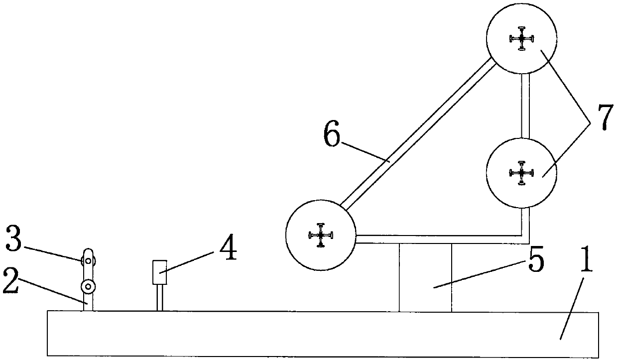
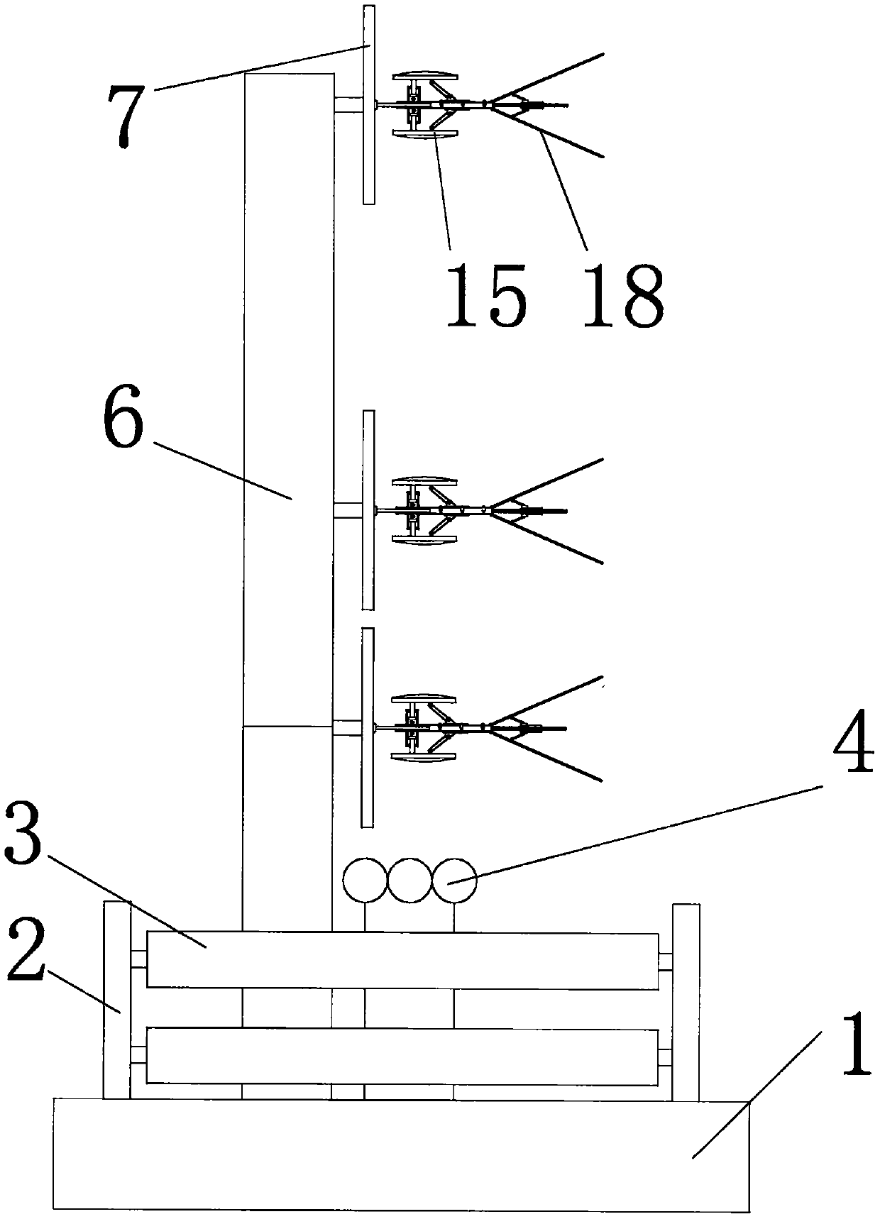
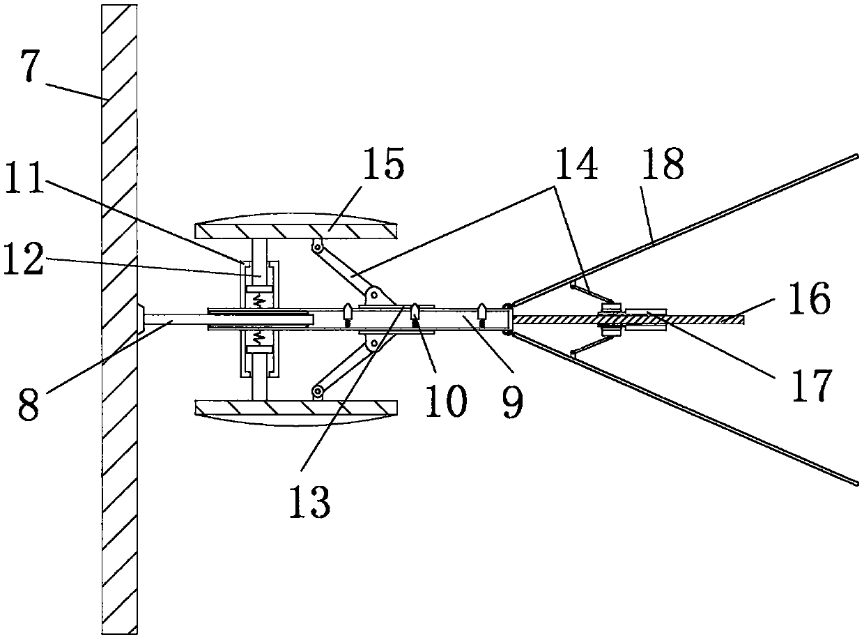
[0024] see Figure 1-5 , the present invention provides a technical solution: a pay-off device for weak current cable construction, including a support base 1, a rotating shaft rod 2, a roller brush 3, a wire combiner 4, a vertical bracket 5, and a triangular bracket 6 , wheel disc 7, horizontal rotating shaft 8, rotating shaft sleeve 9, bump 10, sleeve 11, support rod 12, sliding sleeve 13, connecting rotating rod 14, fixer 15, threaded rod 16, threaded sleev...


PUM


Abstract

The invention discloses a wire unwinding device and a wire unwinding method for weak current cable construction. The wire unwinding device comprises a supporting base, wherein rotating shaft rods arewelded to the edge of the top of the supporting base, the outer walls of the rotating shafts rod are sleeved with roller brushes correspondingly, a wire combiner is fixedly installed at the position,on the side of the rotating shaft rods, of the top of the supporting base, wheel discs are fixedly installed on the side of a triangular support, horizontal rotating shafts are installed in centers ofthe wheel discs through bearings correspondingly, the outer walls of the horizontal rotating shafts are sleeved with rotating shaft sleeves correspondingly, sleeves are fixedly installed on the outerwalls of the sides of the rotating shaft sleeves correspondingly, supporting rods are embedded into the sleeves correspondingly, threaded rods are fixedly installed at the ends of the rotating shaftsleeves correspondingly, and the outer walls of the threaded rods are in threaded connection with threaded sleeves correspondingly. According to the wire unwinding device for the weak current cable construction, cables of different sizes can be arranged more conveniently, the functionality of the device is enhanced, the cleaning capacity of surfaces of the cables is improved, and the surfaces of the cables are not prone to being damaged.

Description

technical field [0001] The invention relates to the technical field of weak-current cable construction, in particular to a wire-releasing device and a wire-releasing method for weak-current cable construction. Background technique [0002] Weak current cables refer to signal and control wires with a working voltage below 36 volts. The biggest feature is low voltage withstand capability and poor overcurrent capability. Thin, easy to get entangled during construction, so a device is needed for sorting and assisting wire-laying operations. [0003] However, the existing weak current cable pay-off device has the following problems: [0004] The weak current cable pay-off device is inconvenient to organize cables of different sizes, which will easily increase the construction time and reduce the construction efficiency, and the functionality of the device is insufficient, and the operation ability for multi-cable pay-off during construction is low , and the ability to clean the...

Claims


Application Information

Patent Timeline
IPC IPC(8): B65H49/20
CPCB65H49/20B65H2701/34
Inventor 彭堂生
Owner 鼎腾(天津)科技发展有限公司
Learn More