
A single wedge locking self-propelled pushing device and method

The technology of locking device and pushing device is applied in the direction of hoisting device, hoisting device, processing of building materials, etc., which can solve the problems of increased workload and low pushing efficiency.

Active Publication Date: 2020-10-23
SHANGHAI CONSTRUCTION GROUP
View PDF6 Cites 0 Cited by
  • Summary
  • Abstract
  • Description
  • Claims
  • Application Information

AI Technical Summary

Problems solved by technology

[0004] Aiming at the problems that the reaction seat used in the existing rail push-slide method relies on manual repeated locking and unlocking movement, which increases the workload and has low push-up efficiency, the purpose of the present invention is to provide a single wedge lock Self-propelled jacking device and method, capable of automatic locking, unlocking and jacking, which improves the automation and work efficiency of jacking construction

Method used


Image

  • A single wedge locking self-propelled pushing device and method
  • A single wedge locking self-propelled pushing device and method
  • A single wedge locking self-propelled pushing device and method

Examples


Embodiment 1

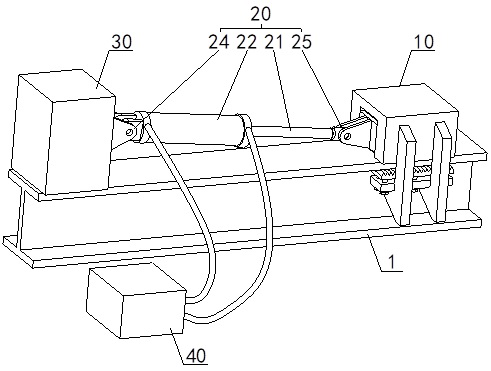
[0038] This embodiment takes the jacking construction of a large steel structure as an example. Figure 1 to Figure 5 The single-wedge locking self-propelled pushing device of the present invention is described, which includes: a single-wedge locking device 10 and a pushing seat 30 arranged at intervals, and a push-off seat arranged between the single-wedge locking device 10 and the pushing seat 30 Push the oil cylinder 20, and the push oil cylinder 20 is connected with the oil circuit of the control center 40;

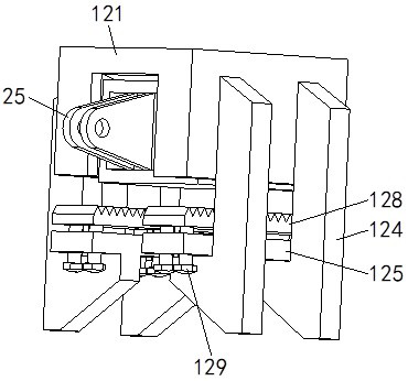
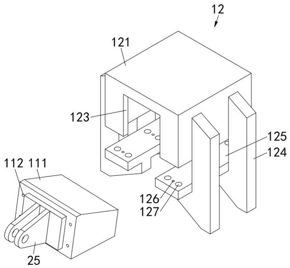
[0039] The single wedge locking device 10 includes an oil cylinder reaction frame 12 and a wedge-shaped slider 111. The oil cylinder reaction frame 12 is clamped and fixed on the rail 1. The oil cylinder reaction frame 12 is provided with a wedge-shaped groove 122 whose bottom surface communicates with the rail 1 along its length direction. , the length direction of the cylinder reaction frame 12 is consistent with the extending direction of the rail 1, the wedge-shap...

Embodiment 2

[0050] combine Figure 1 to Figure 5 Illustrate the self-propelled pushing method of the present invention, concrete steps are as follows:

[0051] S1: if figure 1 As shown, two single-wedge locking self-propelled pushing devices are respectively arranged directly above the track 1 along the center line of the parallel double-track 1, and the single-wedge locking self-propelled pushing devices include single-wedge locking devices arranged at intervals 10 and the push seat 30, and the push cylinder 20 connected between the two, the single wedge locking device 10 includes the cylinder reaction force frame 12 and the wedge-shaped slider 111, and the oil cylinder reaction force frame 12 is clamped and fixed on the track 1, The cylinder reaction force frame 12 is provided with a wedge-shaped groove 122 whose bottom surface communicates with the track along its length direction. The wedge-shaped slider 111 is embedded in the wedge-shaped groove 122 and is hinged with one end of the...


PUM


Abstract

A single-wedge locking self-propelled pushing device and method of the present invention relate to the technical field of building construction. Aiming at the problem that the reaction seat used in the existing rail push-and-slide method relies on manual repeated locking and unlocking, and the pushing efficiency is low. It includes a single-wedge locking device and a push seat arranged at intervals, and a push cylinder between the two. The single-wedge locking device includes a cylinder reaction frame and a wedge-shaped slider. The wedge-shaped slider is embedded in the cylinder reaction The wedge-shaped groove of the force frame can slide along its length direction. The extension of the push cylinder pushes the wedge-shaped slider to slide until it is closely against the track. The single-wedge locking device automatically locks on the track and acts as a counter force seat. The push cylinder reversely pushes the member to be pushed to move one stroke; the push cylinder shrinks and pulls the wedge-shaped slider to slide in reverse until the track is separated, and the single-wedge locking device is automatically unlocked and moves in the direction of push; repeat this process until Complete the pushing construction of the components.

Description

technical field [0001] The invention relates to the technical field of building construction, in particular to a single-wedge locking self-propelled pushing device and method. Background technique [0002] At present, the installation and construction of large-scale steel structures adopts the push-and-slide method. Among them, the rail-driven push-and-slide is to push the rear end of the large-scale steel structure through the horizontal push hydraulic cylinder, and the large-scale steel structure uses the The sliding foot moves along the track to the position to be installed. [0003] When the hydraulic cylinder pushes the large steel structure to move horizontally, the rear end of the hydraulic cylinder needs to be equipped with a reaction force seat that can be locked. After the hydraulic cylinder pushes a stroke, the reaction force seat needs to move a cylinder stroke distance and lock it again , so that the hydraulic cylinder continues to push the next stroke. Howeve...

Claims


Application Information

Patent Timeline
Patent Type & Authority Patents(China)
IPC IPC(8): B66F19/00E04G21/16
CPCB66F19/00E04G21/16
Inventor 龚剑吴联定房霆宸赵一鸣杨佳林左俊卿
Owner SHANGHAI CONSTRUCTION GROUP
Learn More