A grouting valve at the bottom of a cast-in-place pile for geotechnical engineering construction

A technology for geotechnical engineering and cast-in-place piles, which is applied in foundation structure engineering, sheet pile walls, buildings, etc., can solve the problem of difficult filling and other problems, and achieve the effects of wide application range, stable structure and fast grouting speed.

Active Publication Date: 2021-03-30
KUNMING PROSPECTING DESIGN INST OF CHINA NONFERROUS METALS IND
View PDF6 Cites 0 Cited by
  • Summary
  • Abstract
  • Description
  • Claims
  • Application Information

AI Technical Summary

Problems solved by technology

[0003] At present, the grouting valve is generally extended to the bottom of the pile, and the grouting valve is located inside the reinforcement cage. In this way, the concrete sprayed from the grouting valve needs to pass through the reinforcement cage and then contact the soil surface, which is difficult to fully fill. on the soil side of the pile

Method used


Image

  • A grouting valve at the bottom of a cast-in-place pile for geotechnical engineering construction
  • A grouting valve at the bottom of a cast-in-place pile for geotechnical engineering construction
  • A grouting valve at the bottom of a cast-in-place pile for geotechnical engineering construction

Examples


Embodiment Construction

[0027] In order to make the purpose, technical solutions and advantages of the embodiments of the present invention more clear, the technical solutions in the embodiments will be clearly and completely described below in conjunction with the drawings in the embodiments of the present invention. The following embodiments are used to illustrate the present invention , but not to limit the scope of the present invention.

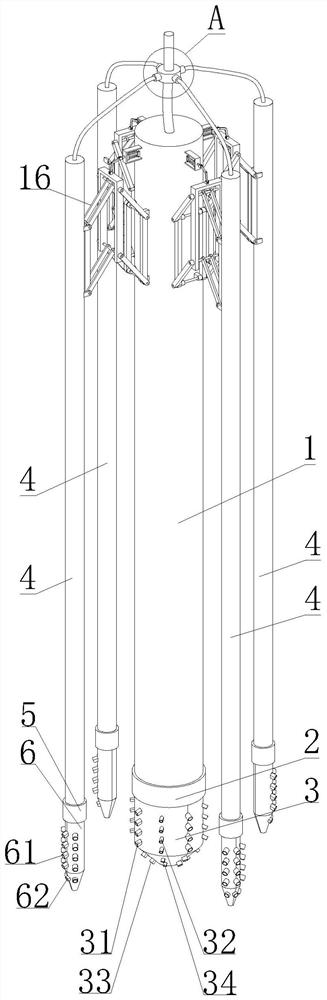
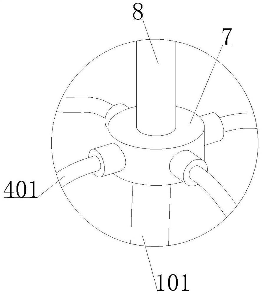
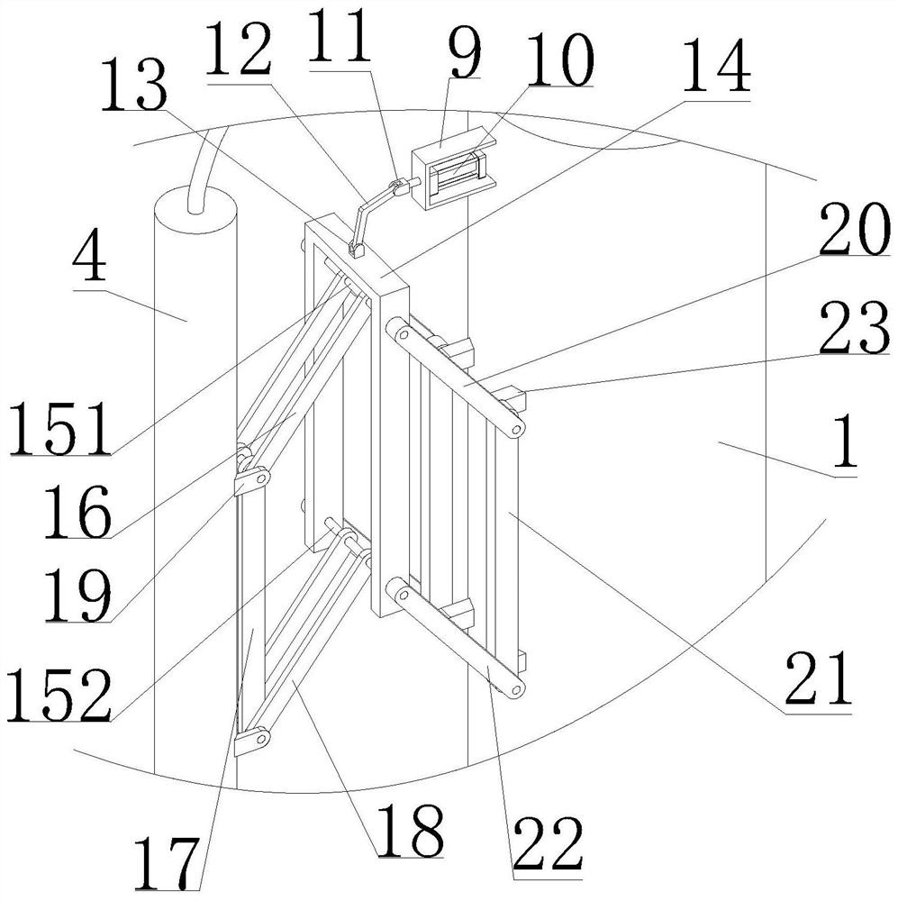
[0028] Such as Figure 1 to Figure 5 As shown, a grouting valve at the bottom of a cast-in-situ pile for geotechnical engineering construction described in this embodiment includes a main cylinder 1, a first connecting sleeve 2, a first connecting cylinder 3, an auxiliary cylinder 4, a second The connecting sleeve 5, the second connecting sleeve 6 and the adjustment assembly; the main cylinder body 1, the first connecting sleeve 2 and the first connecting sleeve 3 are connected sequentially from top to bottom; the lower part of the first connecting sleeve 3 is ...


PUM


Abstract

The invention discloses a grouting valve at the bottom of a cast-in-situ pile for geotechnical engineering construction, which comprises a main cylinder body, a first connecting sleeve, a first connecting sleeve, an auxiliary cylinder body, a second connecting sleeve, a second connecting sleeve and Adjustment assembly; the first discharge hole is provided at the lower part of the first connection cylinder; the fifth discharge hole is provided at the bottom of the second connection cylinder; the adjustment assembly includes a mounting frame, a first connection shaft, a second connection shaft, a first connecting rod, The second connecting rod, the third connecting rod, the first mounting platform, the fourth connecting rod, the fifth connecting rod, the sixth connecting rod and the second mounting platform; the second connecting rod is arranged on the first mounting platform; the first mounting The platform is arranged on the auxiliary cylinder; the fifth connecting rod is arranged on the second installation platform; the second installation platform is arranged on the main cylinder; the main cylinder and the auxiliary cylinder are respectively provided with two parallelogram mechanisms for driving rotation. A drive mechanism that moves the main cylinder and the sub cylinder toward or away from each other. In the present invention, grouting can be performed on both sides inside and outside the reinforcement cage respectively, and the grouting is more uniform and the speed is faster.

Description

technical field [0001] The invention belongs to the technical field of rock engineering, and in particular relates to a grouting valve at the bottom of a cast-in-place pile for rock engineering construction. Background technique [0002] Cast-in-situ pile refers to the pile hole formed in the foundation soil by means of mechanical drilling, steel pipe extrusion or manual excavation at the construction site, and the pile is made by placing a steel cage in it and pouring concrete, depending on the hole-forming method. , Cast-in-situ piles are divided into several categories such as immersed tube piles, bored piles and hole-dug piles. In the prior art, a grouting valve is generally used when pouring cast-in-place piles. [0003] At present, the grouting valve is generally extended to the bottom of the pile, and the grouting valve is located inside the steel cage. In this way, the concrete sprayed from the grouting valve needs to pass through the steel cage and then contact the...

Claims


Application Information

Patent Timeline
Patent Type & Authority Patents(China)
IPC IPC(8): E02D5/62
CPCE02D5/62E02D2250/003E02D2300/002
Inventor 速田勇周罕王良川李继魁邱健彬毛勇成词峰许鹏槐翔英徐德禹张向阳许汉华
Owner KUNMING PROSPECTING DESIGN INST OF CHINA NONFERROUS METALS IND
Why Eureka
Try Eureka