Full-automatic indoor door lock

A fully automatic, door lock technology, applied in the field of locks, can solve the problems of increased cost, poor impact resistance, uneven force, etc., to ensure verticality and smoothness, improve accuracy and reliability, and facilitate on-site installation and use Effect

Inactive Publication Date: 2020-08-14
杭州小安物联科技有限公司
View PDF0 Cites 0 Cited by
  • Summary
  • Abstract
  • Description
  • Claims
  • Application Information

AI Technical Summary

Problems solved by technology

[0004] 1. A set of bevel gear mechanism is usually used to realize the transmission between the output end of the drive motor and the unlocking shaft. On the one hand, the impact resistance is poor, and it is easy to cause impact damage to the bevel gear mechanism due to the impact force when the drive motor rotates. The service life is not high. If metal gears are used to replace conventional plastic gears, the cost will increase significantly. On the other hand, it is easy to ensure the verticality of the transmission commutation due to the uneven force during transmission, which will affect the transmission performance. smoothness, and aggravate the loss of motor power, usually need to choose a larger motor to realize the drive, and then cause the control box to be bulky, which is not conducive to the installation and use on the interior door
[0005] 2. When the lock cylinder is connected to the control box, it only has a limit fixed in one direction. During use, there is a certain amount of mutual deflection between the two, which will affect the relationship between the unlocking shaft in the control box and the shaft of the lock cylinder in the lock cylinder. Concentricity, and ultimately affect the reliability of the unlocking action

Method used


Image

  • Full-automatic indoor door lock
  • Full-automatic indoor door lock
  • Full-automatic indoor door lock

Examples


Embodiment Construction

[0030] The present invention will be described in further detail below in conjunction with the embodiment given with accompanying drawing.

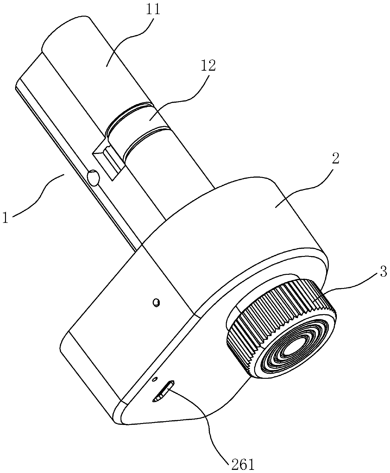
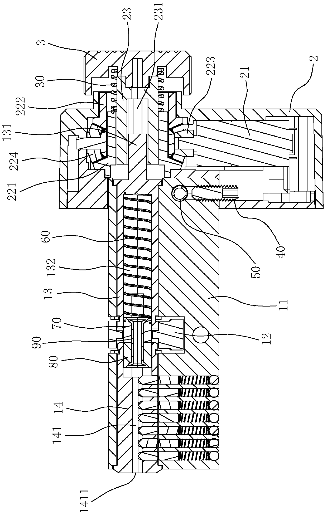
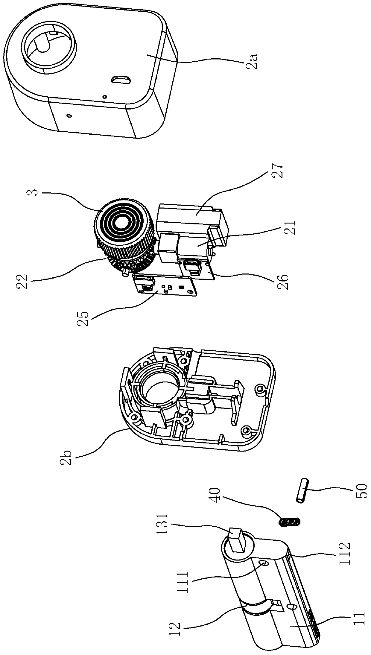
[0031] Such as Figure 1 to Figure 9As shown, a fully automatic indoor door lock according to the embodiment of the present invention includes a lock cylinder 1 and a control box 2, and the lock cylinder 1 includes a lock cylinder housing 11, a lock cylinder dial 12, a lock cylinder rotating shaft 13 and a lock cylinder lock head 14. One end of the lock cylinder housing 11 is connected to the control box 2, the lock cylinder rotating shaft 13 is arranged on the side close to the control box 2 in the lock cylinder housing 11, and the lock cylinder head 14 is arranged in the lock cylinder housing 11 away from the control box 2 One side of the lock cylinder dial 12 is arranged between the lock cylinder rotating shaft 13 and the lock cylinder head 14 and can switch and cooperate with the two. The control box 2 is provided with a driving mot...


PUM


Abstract

The invention relates to a full-automatic indoor door lock. The full-automatic indoor door lock comprises a lock plug and a control box, wherein the lock plug comprises a lock plug shell, a lock plugshifting wheel and a lock plug rotating shaft, one end of the lock plug shell is connected with the control box, and the lock plug rotating shaft is arranged on the side, close to the control box, inthe lock plug shell; a driving motor, a bevel gear transmission mechanism and an unlocking rotating shaft are arranged in the control box, the bevel gear transmission mechanism comprises a first largebevel gear, a second large bevel gear, a driving small bevel gear and at least one driven small bevel gear, the first large bevel gear and the second large bevel gear are oppositely arranged at intervals, and the driving small bevel gear and the driven small bevel gear are evenly distributed in the circumferential direction and engaged with the first large bevel gear and the second large bevel gear; and the driving motor is connected with the driving small bevel gear, the unlocking rotating shaft axially penetrates through the first large bevel gear and the second large bevel gear and is in transmission fit with the first large bevel gear, and the lock plug rotating shaft is in transmission connection with the unlocking rotating shaft. The full-automatic indoor door lock has the advantages of simple structure, small volume, low cost, high reliability, long service life and the like.

Description

technical field [0001] The invention relates to a lockset, in particular to a fully automatic indoor door lock. Background technique [0002] With the continuous development of the "Internet of Things", fully automatic indoor door locks have gradually entered people's field of vision, bringing great convenience and protection to people's lives and safety. Fully automatic indoor door locks are different from traditional mechanical locks. More intelligent door locks in terms of user identification, security, and management, covering specific types of lock products such as fingerprint locks, electronic combination locks, electronic induction locks, networked locks, and remote control locks. [0003] In modern life, automatic indoor door locks are more and more widely used because of their advantages of convenient opening and closing and high safety performance. However, most of the fully automatic indoor door locks currently on the market have the following defects: [0004] 1...

Claims


Application Information

Patent Timeline
Patent Type & Authority Applications(China)
IPC IPC(8): E05B47/00E05B15/00
CPCE05B15/00E05B15/0013E05B47/0012E05B2047/002
Inventor 梅江赵海龙
Owner 杭州小安物联科技有限公司
Why Eureka
Try Eureka