
Integrated fan

A fan and outlet air technology, applied in the direction of mechanical equipment, machine/engine, liquid fuel engine, etc., can solve the problems of large integrated fan, increase the difficulty of overall layout, and inconvenient pipeline arrangement, so as to reduce the production process and improve work Efficiency and stability, the effect of avoiding air turbulence

Pending Publication Date: 2020-08-14
安鼓节能设备(苏州)有限公司
View PDF0 Cites 0 Cited by
  • Summary
  • Abstract
  • Description
  • Claims
  • Application Information

AI Technical Summary

Problems solved by technology

When arranging integrated fans at the production site, the overall layout is often more difficult because of the large size of the integrated fans
[0003] For traditional fans, the air inlet direction and air outlet direction are vertical. Generally, the air inlet is set on the upper end of the fan, and the air outlet is set on the side wall of the fan. The production site needs to set up the air inlet and outlet of the fan. Pipeline, the structure of traditional fans is not convenient for the arrangement of pipelines on site

Method used


Image

  • Integrated fan
  • Integrated fan
  • Integrated fan

Examples


Embodiment Construction

[0026] The following will clearly and completely describe the technical solutions in the embodiments of the present invention with reference to the accompanying drawings in the embodiments of the present invention. Obviously, the described embodiments are only some, not all, embodiments of the present invention. Based on the embodiments of the present invention, all other embodiments obtained by persons of ordinary skill in the art without making creative efforts belong to the protection scope of the present invention.

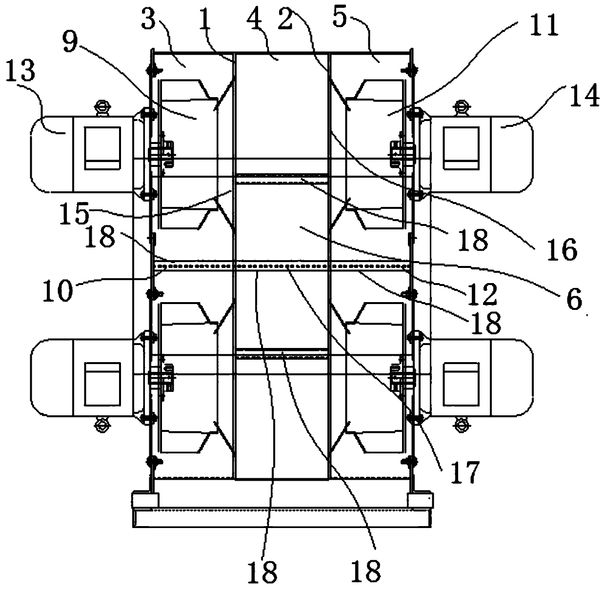
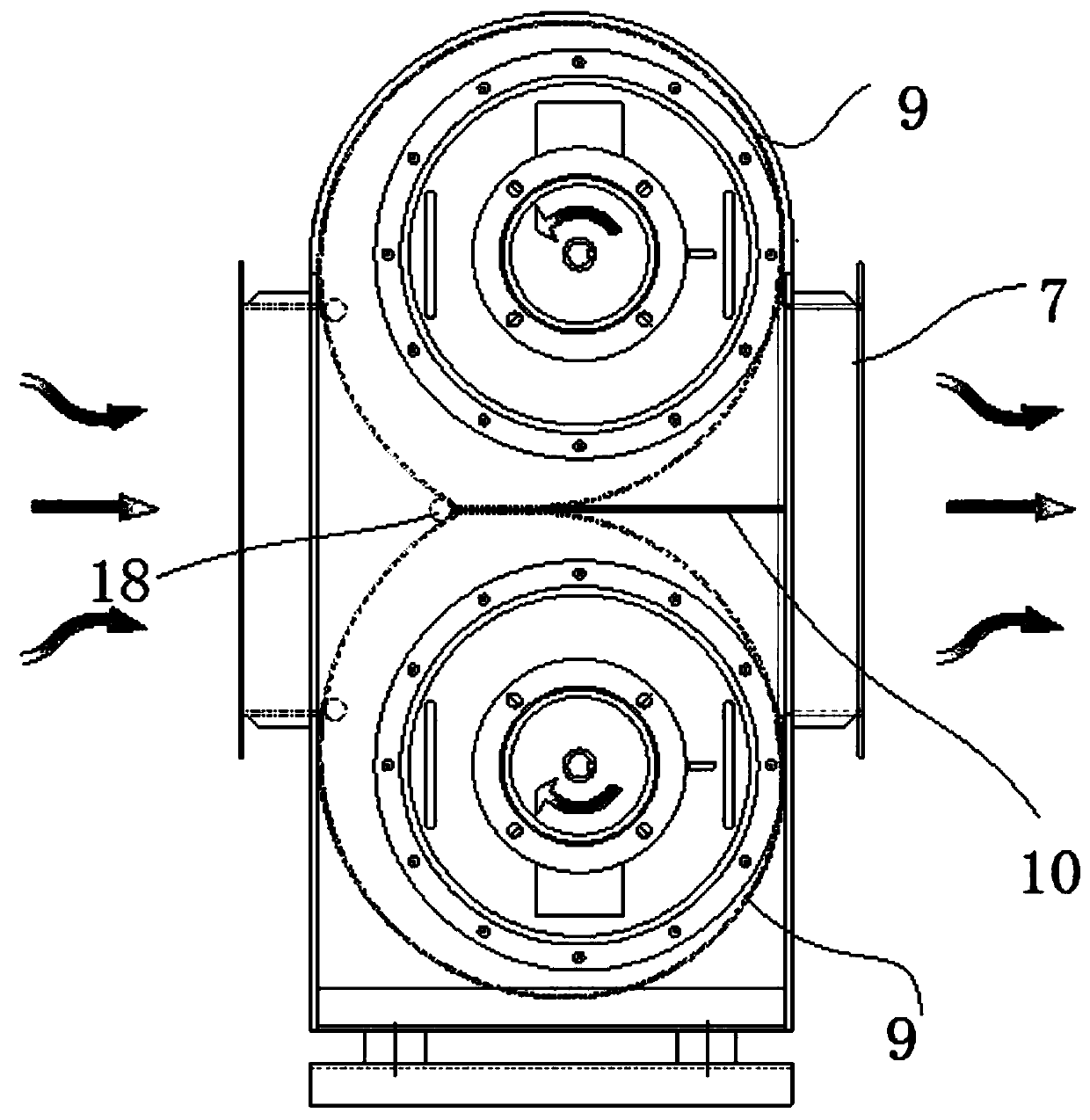
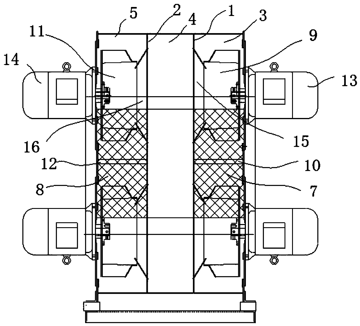
[0027] Reference attached Figure 1-3 , this embodiment provides an integrated fan, including a housing, two first impellers 9 , two second impellers 11 , two first motors 13 and two second motors 14 .

[0028] The housing includes first and second sidewalls opposite along a first horizontal direction, and third and fourth sidewalls opposite along a second horizontal direction. The first side wall, the second side wall, the third side wall and the fourth side...


PUM


Abstract

The invention discloses an integrated fan. The integrated fan comprises a shell, two first flow guide pipes, two first impellers and a first flow guide plate; the shell comprises a first side wall, asecond side wall and a first partition plate, wherein the first side wall and the second side wall are opposite, and the first partition plate is arranged in the shell and divides the shell into a first cavity and an air inlet cavity; the first side wall is provided with an air inlet communicating with the air inlet cavity, the second side wall is provided with a first air outlet communicating with the first cavity, and the first partition plate is provided with two first communicating holes; the two first flow guide pipes are installed on the first partition plate and communicate with the corresponding first communicating holes; the two first impellers are arranged in the first cavity and communicate with the corresponding first flow guide pipes, and the two first impellers rotate synchronously in the opposite directions; and the first guide plate is arranged between the two first impellers, and the upper end face and the lower end face of the first guide plate face the output ends ofthe two first impellers correspondingly. The integrated fan is small in size, convenient to transport and use, high in working stability and higher in efficiency.

Description

technical field [0001] The invention relates to the technical field of gas conveying mechanical equipment, in particular to an integrated fan. Background technique [0002] Integrated fans are widely used in ventilation, dust removal, cooling and other processes in various fields. When arranging integrated fans at the production site, the difficulty of the overall layout is often increased due to the large size of the integrated fans. [0003] For traditional fans, the air inlet direction and air outlet direction are vertical. Generally, the air inlet is set on the upper end of the fan, and the air outlet is set on the side wall of the fan. The production site needs to set up the air inlet and outlet of the fan. Pipeline, the structure of traditional fans is not convenient for the arrangement of pipelines on site. [0004] Because, it is necessary to develop a new integrated fan, which has solved the above technical problems. Contents of the invention [0005] In order ...

Claims


Application Information

Patent Timeline
Patent Type & Authority Applications(China)
IPC IPC(8): F04D25/16F04D25/08F04D29/42F04D29/44F04D29/62F04D29/66
CPCF04D25/166F04D25/08F04D29/4213F04D29/4246F04D29/441F04D29/626F04D29/667
Inventor 王芬耿军喜
Owner 安鼓节能设备(苏州)有限公司
Learn More