Rotating shaft supporting structure, display device and assembling method thereof

A technology of supporting structure and rotating shaft, applied in the direction of identifying devices, shafts, shafts and bearings, etc., can solve the problems of reducing the user's operating experience, affecting the surface flatness, poor touch feeling, etc., to solve the problem of slippage gap and crease. Improve and solve the effect of easy warping

Active Publication Date: 2020-08-14
BOE TECH GRP CO LTD
View PDF5 Cites 7 Cited by
  • Summary
  • Abstract
  • Description
  • Claims
  • Application Information

AI Technical Summary

Problems solved by technology

However, at present, flexible display panels still face many problems. For example, when the flexible display panel is flattened after repeated folding and bending, the bending area of ​​the flexible display panel is easy to warp and cause c

Method used


Image

  • Rotating shaft supporting structure, display device and assembling method thereof
  • Rotating shaft supporting structure, display device and assembling method thereof
  • Rotating shaft supporting structure, display device and assembling method thereof

Examples


Embodiment Construction

[0061] Example embodiments will now be described more fully with reference to the accompanying drawings. Example embodiments may, however, be embodied in many forms and should not be construed as limited to the embodiments set forth herein; rather, these embodiments are provided so that this disclosure will be thorough and complete, and will fully convey the concept of example embodiments to those skilled in the art. The same reference numerals in the drawings denote the same or similar structures, and thus their detailed descriptions will be omitted.

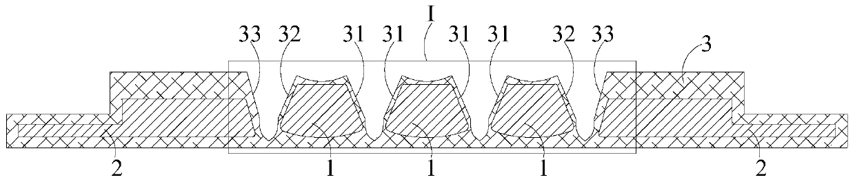
[0062] In the related art, the problem of warping in the bending area of ​​the flexible display panel is solved by adding a steel sheet in the shaft area and adding a magnet in the middle frame, and the magnet absorbs the steel sheet. Adding steel sheets in the hinge area can improve the resilience of the display panel, solve the warping problem in the bending area to a certain extent, and ensure the flatness of the whole mach...


PUM

PropertyMeasurementUnit
Lengthaaaaaaaaaa
Widthaaaaaaaaaa

Abstract

The invention relates to the technical field of display, and provides a rotating shaft supporting structure, a display device and an assembling method. The rotating shaft supporting structure comprises a rigid supporting part. The rigid supporting part comprises a plurality of rigid supporting strips arranged in parallel. A first gap is arranged between every two adjacent rigid supporting strips.The length direction of the rigid supporting strips is perpendicular to the bending direction of a flexible display panel. The orthographic projection of the rigid supporting part on the flexible display panel is located in the bending area. Two first supporting plates are arranged in parallel with the rigid supporting strips and are correspondingly located on the two opposite sides of the rigid supporting part. A second gap is arranged between the first supporting plates and the rigid supporting part. The orthographic projection of the first supporting plates on the flexible display panel islocated in a straight area. A flexible coating layer wraps the rigid supporting part and the supporting plates. One side, close to the flexible display panel, of the rigid supporting part is connected with one side, close to the flexible display panel, of the supporting plate into a whole. The bending area of the flexible display panel is not prone to warping.

Description

technical field [0001] The present invention relates to the field of display technology, in particular to a rotating shaft supporting structure, a display device including the rotating shaft supporting structure, and an assembly method of the display device. Background technique [0002] Nowadays, flexible display panels have gradually entered the field of vision of consumers, and the foldability of flexible display panels has greatly expanded the application fields of display panels. However, at present, flexible display panels still face many problems. For example, when the flexible display panel is flattened after repeated folding and bending, the bending area of ​​the flexible display panel is easy to warp and cause creases, which affects the overall surface flatness; Warping is also prone to the problem of poor tactility caused by film layer separation, and in severe cases, it will cause screen damage, thereby reducing the user's operating experience. [0003] Therefor...

Claims


Application Information

Patent Timeline
IPC IPC(8): F16C11/12G09F9/30
CPCF16C11/12G09F9/301F16C2370/20G06F1/1652G06F1/1616G06F1/1681G06F1/1607H05K5/0204
Inventor 孙宝锋祝尚杰
Owner BOE TECH GRP CO LTD
Why Eureka
Try Eureka