Extractor hood

A technology of range hood and fan rack, applied in the direction of removing range hood, household stove/stove, heating method, etc., can solve the problems of reducing the delicacy of the whole machine and increasing the difficulty of cleaning for users, so as to prolong the service life and avoid accidents. Drop, meet the effect of oil circuit and sealing

Active Publication Date: 2020-08-14
NINGBO FOTILE KITCHEN WARE CO LTD
View PDF14 Cites 3 Cited by
  • Summary
  • Abstract
  • Description
  • Claims
  • Application Information

AI Technical Summary

Problems solved by technology

Due to the fact that the fan system in the fume collecting hood and the wind cabinet are independent of each other in this structure, the oil thrown out by the fan system will drip without going through the telescopic shell. The oil cup will not only reduce the delicacy of the whole machine, but also greatly increase the difficulty of cleaning for users

Method used


Image

  • Extractor hood
  • Extractor hood
  • Extractor hood

Examples


Embodiment 1

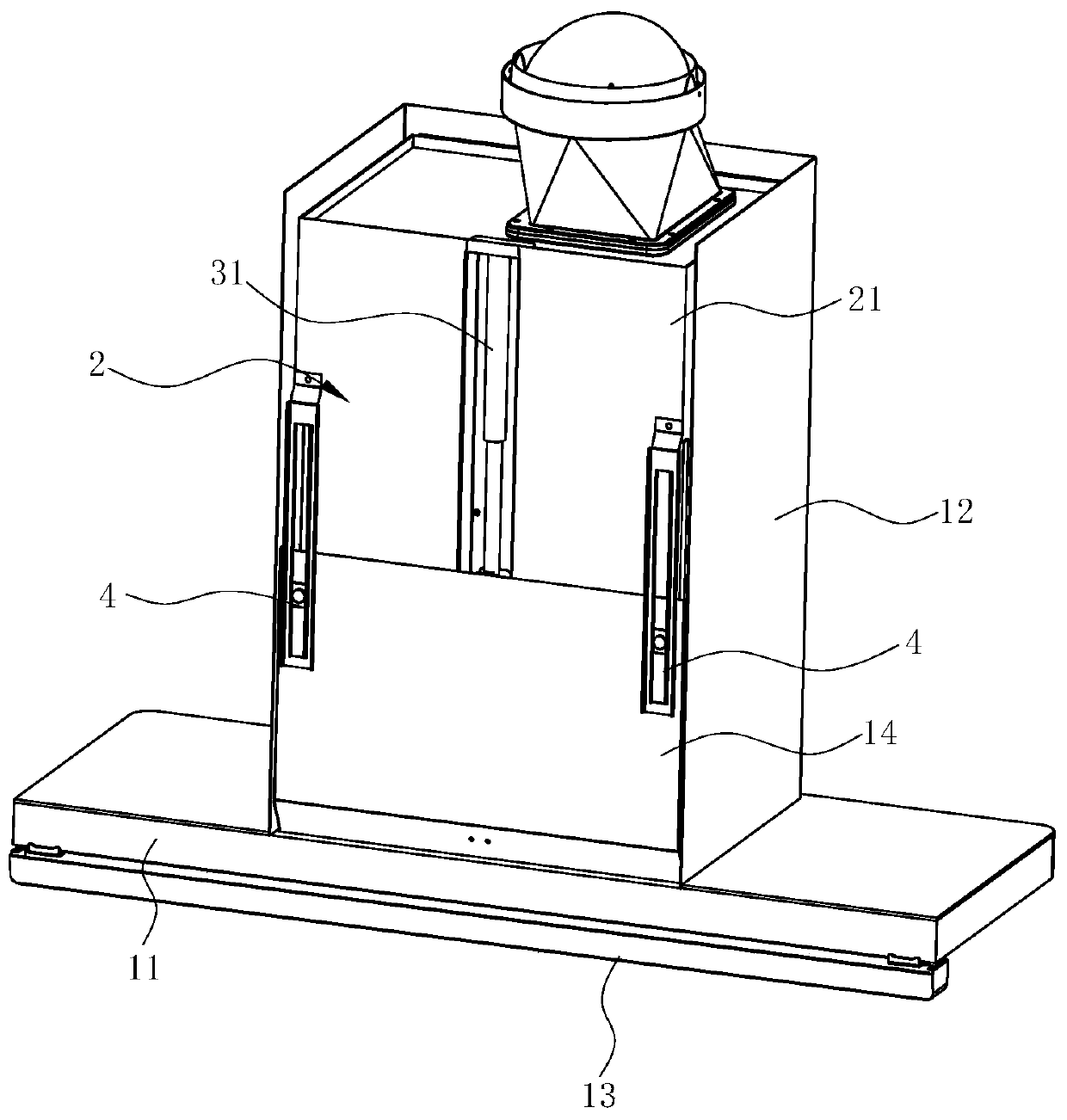
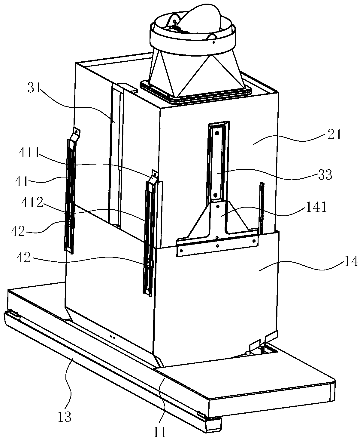
[0051] see image 3 , Figure 4 , Figure 7 and Figure 8 , the range hood also includes a movement mechanism for driving the movable part 1 to move up and down relative to the fixed part 2 , which is a manual movement mechanism, including a balance device 31 , a transmission mechanism 32 and a guide mechanism 33 . Wherein, the balancing device 31 is preferably a pneumatic spring, which is arranged on the rear side of the fan frame 21 and extends in the longitudinal direction. The upper end of the housing of the pneumatic spring is connected and fixed with the fan frame 21, and the telescopic rod 311 of the pneumatic spring can be retracted upward or extended downward. The transmission mechanism 32 includes a sliding block 322 , which is arranged on the telescopic rod 311 of the pneumatic spring, preferably at the end of the telescopic rod 311 , and the sliding block 322 is also connected and fixed with the moving frame 14 . When the user pushes the movable part 1, such as...

Embodiment 2

[0065] see Figure 18 and Figure 19 , the difference from the above-mentioned first embodiment is that the balance device 31 and the transmission mechanism 32 of the motion mechanism are different. In this embodiment, the balance device 31 is a damper composed of coil springs, and the transmission mechanism 32 includes a rotating set on the balance device 31. The gear 323 on the central axis of the fan frame 323, the rack 324 meshing with the gear 323, the first link 325, the second link 326, the first chute 327 arranged on the rear side of the fan frame 21 and the rear of the moving frame 14 The second chute 328 on the side. The first chute 327 is preferably close to the upper part of the rear side of the fan frame 21 , and the second chute 328 is preferably close to the upper part of the rear side of the moving frame 14 . Both the first chute 327 and the second chute 328 extend in the left-right direction and are parallel to each other, preferably, they are both horizonta...


PUM


Abstract

The invention discloses an extractor hood. A movable component, a fixed component and a motion mechanism used for manually driving the movable component to ascend and descend relative to the fixed component are included. The movable component comprises a smoke gathering cover. The fixed component comprises a draught fan frame. The extractor hood is characterized in that the movable component further comprises a motion frame arranged above the smoke gathering cover, the smoke gathering cover is provided with an air inlet, the lower end of the motion frame is connected to the periphery of the air inlet, and the motion frame wraps the periphery of the draught fan frame. Compared with the prior art, the extractor hood has the advantages that the motion frame of the movable component wraps theperiphery of the draught fan frame of the fixed component, the oil path and seal requirements can be met, through only arrangement of one oil gathering component, grease collection can be achieved, and oil dripping in the extractor hood shutdown state is avoided; and through the arrangement of a supporting component, movable component damage due to friction with a wall in the lifting movement process can be avoided, the motion resistance is reduced, and the service life is prolonged.

Description

technical field [0001] The invention relates to a lampblack purification device, in particular to a lampblack machine. Background technique [0002] Range hoods have become one of the indispensable kitchen appliances in modern homes. The range hood uses the principle of fluid dynamics to work. The centrifugal fan installed inside the range hood sucks and discharges the oil fume, and uses the filter screen to filter some grease particles. The centrifugal fan includes a volute, an impeller installed in the volute, and a motor that drives the impeller to rotate. When the impeller rotates, a negative pressure suction is generated in the center of the fan, and the oil fume under the range hood is sucked into the fan. After being accelerated by the fan, it is collected by the volute and guided out of the room. [0003] At present, common range hoods on the market include top suction and side suction. The top suction range hood adopts the principle of oil fume ascending, which g...

Claims


Application Information

Patent Timeline
Patent Type & Authority Applications(China)
IPC IPC(8): F24C15/20
CPCF24C15/20F24C15/2085
Inventor 邹志锋申志贤徐鑫张上国王磊
Owner NINGBO FOTILE KITCHEN WARE CO LTD
Why Eureka
Try Eureka