
Ventilation model internal resistance supporting and measuring system

A measurement system and model technology, which is applied in the field of aerodynamic test equipment and wind tunnel experimental equipment, can solve the problems such as the inability to realize the precise installation of the tail pressure measuring rake

Active Publication Date: 2020-08-14
INST OF HIGH SPEED AERODYNAMICS OF CHINA AERODYNAMICS RES & DEV CENT
View PDF10 Cites 17 Cited by
  • Summary
  • Abstract
  • Description
  • Claims
  • Application Information

AI Technical Summary

Problems solved by technology

[0006] In the above-mentioned existing technologies, the precise installation of the tail pressure measuring rake cannot be realized, especially in the targeted and precise adjustment of the installation position of the pressure measuring steel pipe for measuring static pressure or total pressure. In view of this, for Further technical and device innovations are required on the technical issue of how to reduce the influence of the pressure measurement rake installation precision adjustment and support device on the ventilation model during the aerodynamic measurement process

Method used


Image

  • Ventilation model internal resistance supporting and measuring system
  • Ventilation model internal resistance supporting and measuring system
  • Ventilation model internal resistance supporting and measuring system

Examples


Embodiment 1

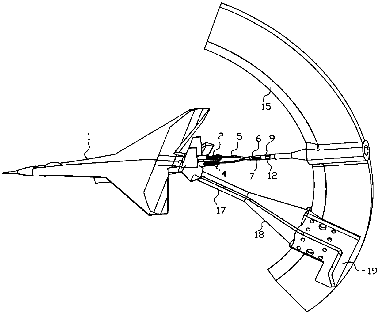
[0122] Combined with the manual image 3 with Figure 4 The ventilation model internal resistance support measurement system shown includes a scimitar mechanism 15 installed in the wind tunnel, one end is fixedly connected to the scimitar mechanism 15, the other end is connected to and supports the abdominal support mechanism of the tested model 1, and is installed on the model 1 The leeward direction is used to measure the internal resistance of the model 1 and is connected to the scimitar mechanism 15. A balance is coaxially installed in the model 1. The pseudo-tail mechanism includes a pole and is connected to the pole freely. The pressure measuring rake at the end, the strut is composed of the front section 6 of the false tail branch, the middle section 9 of the false tail branch and the tail section 13 of the false tail branch; , the radial and horizontal relative positions of the false tail branch middle section 9 and the false tail branch tail section 13 are detachable...

Embodiment 2

[0139] As a preferred embodiment of the application, in conjunction with the description attached Figure 3-4 , Figure 9 As shown, on the basis of the structure and principle of Example 1, in order to further expand the practicability of the pressure measurement rake and the compatibility of pressure measurement for tail nozzles with different cross-sectional sizes, the pressure measurement rake includes a The front section 6 is connected to the pressure measuring rake support 4 in the shape of "ten" or "X". The pressure measuring rake support 4 is slidably connected with a slider 3 for installing the pressure measuring steel pipe 2, and any slider 3 is installed There are at least two piezometric steel pipes 2 . The fixed pressure measuring rake is usually only applicable to a single nozzle of model 1. For tail nozzles of different cross-sections or when the nozzle of the same model 1 is in different states of expansion or convergence, the setting of slider 3 can move the p...

Embodiment 3

[0141] On the basis of Embodiment 2, this embodiment takes double pressure measuring rakes as an example, and further combines the Figure 3-10 As shown, the false tail branch front fork 5 is connected between the false tail branch front section 6 and the pressure measurement rake bracket 4, and the false tail branch front fork 5 has at least one end connected to the pressure measurement rake bracket 4; The front section 6 of the branch and the middle section 9 of the false tail branch are plugged together, and the front section 6 of the false tail branch is provided with at least one transverse strip-shaped hole 7 along the axial direction, and at least one of the false tail branches is arranged in any transverse strip-shaped hole 7. Branch middle section 9 threaded connections are used to fix the relative position fasteners of false tail branch front section 6 and false tail branch middle section 9 . When it is necessary to adjust the axial distance between the front section...


PUM

PropertyMeasurementUnit
Outer diameteraaaaaaaaaa
The inside diameter ofaaaaaaaaaa

Abstract

The invention discloses a ventilation model internal resistance supporting and measuring system. The system comprises a bent knife mechanism installed in a wind tunnel, an abdomen supporting mechanismand a false tail support mechanism. One end of the abdomen supporting mechanism is fixedly connected to the bent knife mechanism, the other end of the abdomen supporting mechanism is connected with and supports a tested model, the false tail support mechanism is installed in the downwind direction of the model, is used for measuring the internal resistance of the model and is connected to the bent knife mechanism, a balance is coaxially installed in the model, the false tail support mechanism comprises a supporting rod and a pressure measuring rake connected to the free end of the supportingrod, and the supporting rod is composed of a false tail support front section, a false tail support middle section and a false tail support tail section; and the axial relative positions of the falsetail support front section and the false tail support middle section are detachably adjusted, and the radial and horizontal relative positions of the false tail support middle section and the false tail support tail section are detachably adjusted. Axial and radial multi-angle adjustment of the pressure measuring rake can be achieved through the false tail support, and the problem of measurement data distortion caused by installation errors of the pressure measuring rake and a tail nozzle is solved.

Description

technical field [0001] The invention relates to the field of aerodynamic test devices, in particular to the field of wind tunnel test devices, and in particular to a ventilation model internal resistance support measurement system. Background technique [0002] When conducting full-scale conventional force tests of aircraft and missiles in a high-speed wind tunnel, the air inlet of the model is generally blocked with a blocking cone, and such a model is called a non-ventilated model or a blocking cone model. The airless model cannot simulate the flow state near the air inlet during real flight, nor can it simulate the flow state near the engine tail nozzle, so the aerodynamic data obtained with the airless model are different from the aerodynamic data obtained by the aircraft during real flight . The ideal test method is to use a model with an engine simulator to conduct wind tunnel tests to simultaneously simulate the intake and jet flow regimes. However, due to the comple...

Claims


Application Information

Patent Timeline
IPC IPC(8): G01M9/06
CPCG01M9/06G01M9/062
Inventor 刘祥徐扬帆王红彪庞超刘大伟史晓军陈植
Owner INST OF HIGH SPEED AERODYNAMICS OF CHINA AERODYNAMICS RES & DEV CENT
Learn More