Device and method for testing real fire of compression member

A technology of pressure components and test devices, which is applied in the field of real fire test devices for pressure components, can solve the problems of more restricted conditions of use, effects of flame radiation, differences, etc., and achieve convenient use, low cost, and reliable theoretical analysis Effect

Active Publication Date: 2020-08-14
SHANGHAI RES INST OF BUILDING SCI CO LTD
View PDF6 Cites 0 Cited by
  • Summary
  • Abstract
  • Description
  • Claims
  • Application Information

AI Technical Summary

Problems solved by technology

However, the standard fire test furnace can only simulate the behavior of the components after the indoor fire flashover, and can only simulate the physical behavior of the components during the heating process of the fire, and the components are basically in a uniform fire state
However, the development of an actual building fire is a very complicated process. The initial stage of a real fire is a local fire at the ignition point. For compressed components such as columns and walls, the smoke temperature distribution around the components is uneven, mainly due to local flame radiation. Function; when the combustibles in the room are burned out, the fire will enter the decay stage, and the behavior of the components under the real fire is quite different from the physical behavior measured by the standard test furnace
Due to the high construction cost of the test furnace, there are many restrictions on the use conditions

Method used


Image

  • Device and method for testing real fire of compression member
  • Device and method for testing real fire of compression member
  • Device and method for testing real fire of compression member

Examples


Embodiment Construction

[0035] The specific embodiments of the present invention will be further described in detail below with reference to the accompanying drawings.

[0036] In order to make the objectives, technical solutions and advantages of the present invention clearer, the present invention will be further described in detail below with reference to the accompanying drawings and embodiments.

[0037] The length of the wooden column (compression member 12 ) in the present invention is 1.5 meters, and the side length is 0.4 meters.

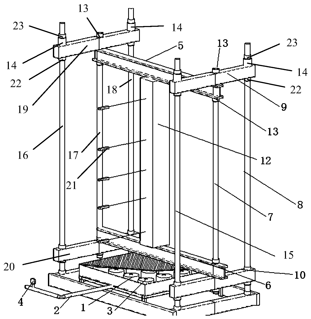
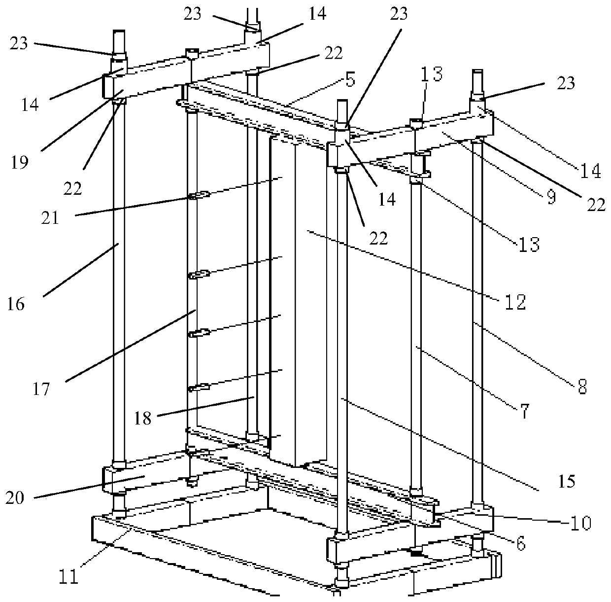
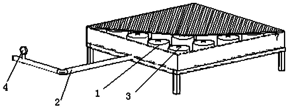
[0038] refer to Figure 1 to Figure 4 The real fire test device for pressure components shown is composed of a fire simulation device, a loading device and a data acquisition device. The fire simulation device is composed of a burner 1, a gas pipeline 2, an ignition system 3 and a gas flow valve 4. The gas pipeline 2 supplies combustion fuel to the burner 1, and the gas flow rate valve 4 is used to monitor and control the flow rate of the gas.

[0039] The loadi...


PUM


Abstract

The invention discloses a device and a method for testing a real fire of a compression member. The device comprises a fire source simulation device, a compression member loading device and a data acquisition device. The compression member loading device comprises a lower cross beam of which two ends are respectively connected with a first lower side cross beam and a second lower side cross beam and an upper cross beam of which two ends are respectively connected with a first upper side cross beam and a second upper side cross beam; the two ends of the first upper side beam and the first lowerside beam are screwed to upper and lower ends of a first screw rod and a second screw rod and the middle parts of the first upper side cross beam and the first lower side cross beam are in threaded connection with the upper and lower ends of a third screw rod; two ends of the second upper side cross beam and a second lower side cross beam are screwed with upper and lower ends of fourth and fifth screw rods, and the middle parts of the second upper side cross beam and the second lower side cross beam are screwed with upper and lower ends of a sixth screw rod; a screwing nut is arranged on eachscrew rod at the screw joint, and a pressure sensor is selectively arranged between the nut and the first and second upper side edge cross beams; a pressed test piece to be tested is vertically clamped between the lower cross beam and the upper cross beam; and a fire source of a fire source simulation device is arranged below the lower cross beam.

Description

technical field [0001] The invention belongs to the technical field of fire test devices, and in particular relates to a real fire test device of a pressure-receiving member and a test method using the test device. Background technique [0002] Fire is one of the most frequent and devastating disasters, and its frequency ranks first among all disasters. Fires such as the Jiaozhou Road apartment fire in Shanghai, the Grenfell Tower apartment fire in London, and Notre Dame de Paris fire caused heavy casualties and economic and cultural losses to people. Therefore, the fire safety of engineering structures is an important aspect of structural safety. At present, the main experimental research on structural behavior under fire is to use a fire test furnace, which is a closed space. The heating curve in the furnace is controlled by controlling the amount of gas in the closed space, the pressure in the furnace, and the air in the furnace to simulate the effect of fire. The furna...

Claims


Application Information

Patent Timeline
Patent Type & Authority Applications(China)
IPC IPC(8): G01M99/00G09B9/00
CPCG01M99/00G09B9/00
Inventor 陈玲珠许清风郑乔文王卓琳王明谦冷予冰
Owner SHANGHAI RES INST OF BUILDING SCI CO LTD
Why Eureka
Try Eureka