A flow mixing device arranged in the descending section of the integrated reactor pressure vessel

A technology for pressure vessels and reactors, which is used in reactors, cooling devices, and greenhouse gas reduction to achieve uniform temperature and pressure and ensure safe operation.

Active Publication Date: 2022-04-29
HARBIN ENG UNIV
View PDF12 Cites 0 Cited by
  • Summary
  • Abstract
  • Description
  • Claims
  • Application Information

AI Technical Summary

Problems solved by technology

[0005] In order to solve the above problems, the object of the present invention is to propose a device capable of realizing the mixing of coolant in the descending section of the integrated reactor pressure vessel, which is used to solve the problem of uneven temperature distribution of the coolant at the core inlet caused by the group operation of once-through steam generators , improve the safety of reactor operation, the invention content of the present invention is as follows:

Method used


Image

  • A flow mixing device arranged in the descending section of the integrated reactor pressure vessel
  • A flow mixing device arranged in the descending section of the integrated reactor pressure vessel
  • A flow mixing device arranged in the descending section of the integrated reactor pressure vessel

Examples


Embodiment 1

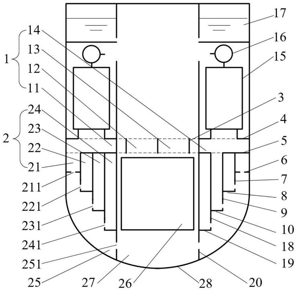
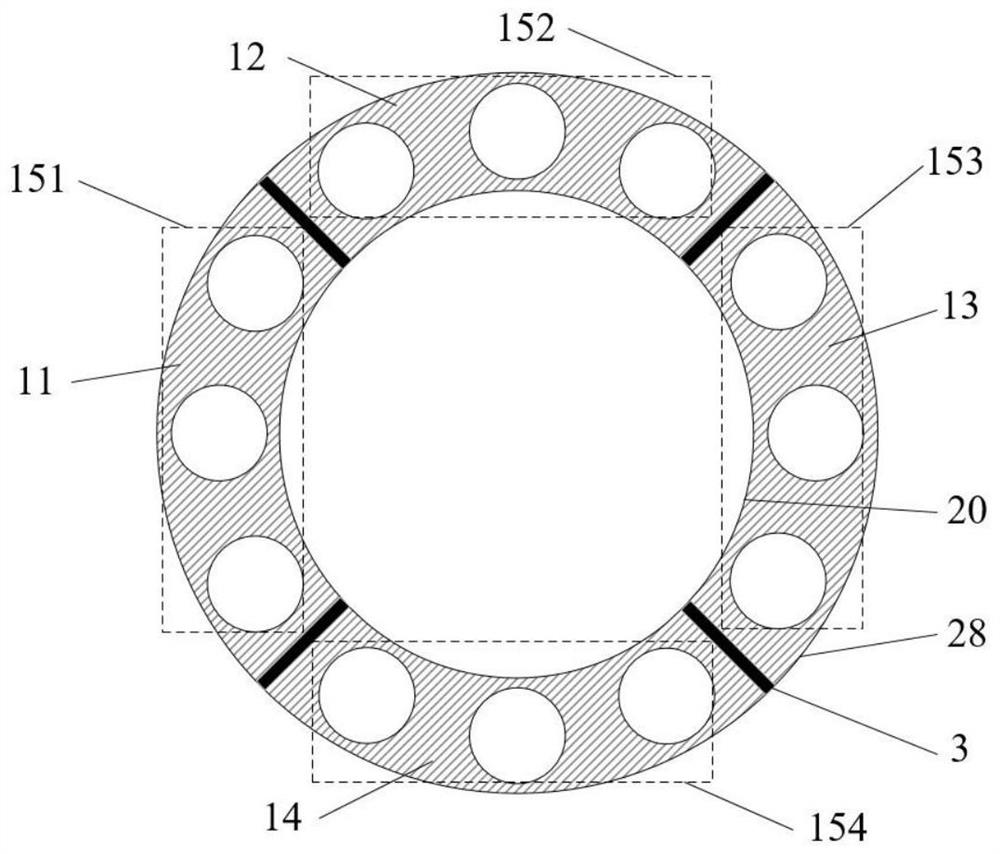
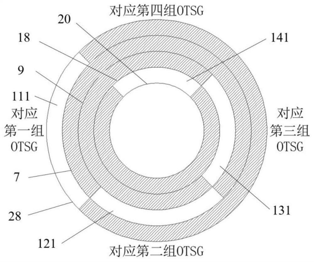
[0030]A flow mixing device arranged in the descending section of the integrated reactor pressure vessel, including a flow distribution part 1 and a flow mixing part 2; the flow distribution part 1 is arranged on the inner wall of the integrated reactor pressure vessel, including: an annular shape with upper and lower gaps The inlet annular dividing plate 4 and the outlet annular dividing plate 5, the annular vertical baffle plate 20 arranged on the inner ring of the inlet annular dividing plate 4 and the outlet annular dividing plate 5, and form an annular airtight cavity; the annular airtight cavity is provided with N Evenly arranged vertical partitions 3, N≥2, form N fan-shaped spaces; the upper end of each fan-shaped space is correspondingly provided with a DC steam generator connected thereto; in this embodiment, N is preferably 4.

[0031] Such as figure 1 As shown, this embodiment is an embodiment of a flow mixing device arranged in the descending section of the integrat...


PUM


Abstract

The invention discloses a flow mixing device arranged in the descending section of an integrated reactor pressure vessel, which belongs to the technical field of nuclear reactor engineering and includes a flow distribution part and a flow mixing part; the flow distribution part includes: an inlet annular partition and an outlet annular partition, An annular vertical baffle plate forms an annular airtight cavity with the inner wall of the reactor pressure vessel; N evenly arranged vertical partitions are arranged in the annular airtight cavity to form N fan-shaped spaces; the upper end of each fan-shaped space is correspondingly provided with The direct-flow steam generator connected with it; the flow mixing component includes: an annular flow channel; the annular flow channels are all provided with flow channel outlet holes. The flow mixing device in the descending section of the integrated reactor pressure vessel of the present invention utilizes the space in the descending section of the integrated reactor pressure vessel, and realizes the change of the flow direction of the coolant by adding horizontal partitions and vertical partitions to achieve the purpose of flow mixing , will not change other structural designs of the integrated reactor system.

Description

technical field [0001] The invention belongs to the technical field of nuclear reactor engineering, and in particular relates to a flow mixing device arranged in the descending section of an integrated reactor pressure vessel. Background technique [0002] The integrated reactor arranges the main components of the primary circuit system such as the core, steam generator, main pump and pressurizer inside the pressure vessel. This arrangement cancels the main pipeline and improves the inherent safety of the reactor. In order to improve the natural circulation capacity of the coolant, generally multiple once-through steam generators are arranged in the annular gap between the core basket and the pressure vessel. Therefore, the descending section of the integrated reactor pressure vessel is compared with the decentralized arrangement of the reactor pressure vessel. The flow cross section of the descending section is much larger. Moreover, the coolant from the outlet of the once...

Claims


Application Information

Patent Timeline
Patent Type & Authority Patents(China)
IPC IPC(8): G21C15/18G21C15/26
CPCG21C15/18G21C15/26Y02E30/30
Inventor 夏庚磊李韧彭敏俊薛若军王航成守宇朱海山杜雪
Owner HARBIN ENG UNIV
Why Eureka
Try Eureka