A waist-worn energy storage rehabilitation walker
What is Al technical title?
Al technical title is built by PatSnap Al team. It summarizes the technical point description of the patent document.
A walker and energy storage technology, which can be used in appliances to help people move around, physical therapy, etc. It can solve the problems of unsound upper limbs, loss of limb function, and laborious legs, and achieve a small overall weight and increase the stiffness coefficient. , easy to carry and wear
Active Publication Date: 2022-02-15
邯郸市丛台区泽端科技服务有限公司
View PDF10 Cites 0 Cited by
Summary
Abstract
Description
Claims
Application Information
AI Technical Summary
This helps you quickly interpret patents by identifying the three key elements:
Problems solved by technology
Method used
Benefits of technology
Problems solved by technology
If the patient stays in bed for a long time, it will cause muscle atrophy, joint aging, bedsore, and further loss of limb function, which is not conducive to the early recovery of the body
For patients with unilateral lower limb motor dysfunction, since the other lower limb is healthy and has the ability to stand, rehabilitation exercises should be performed as soon as possible to allow the limb with motor dysfunction to move. There are many ways to move, including self-help walking Or walking with the assistance of an accompanying person is a good way of moving, but when walking independently, the lower limbs with motor dysfunction cannot fully apply force, and the legs are strenuous and cannot walk normally. This requires the use of a walker. In the prior art Most of the walkers are four-legged walkers with wheels, but it is not convenient for patients with incomplete upper limbs or injuries
Method used
Image
Click on the blue label to locate the original text in one second.
Reading with bidirectional positioning of images and text.
Examples
Embodiment Construction
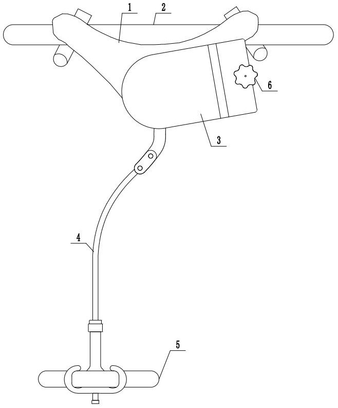
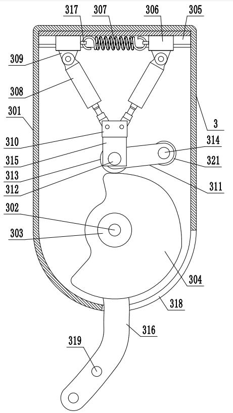
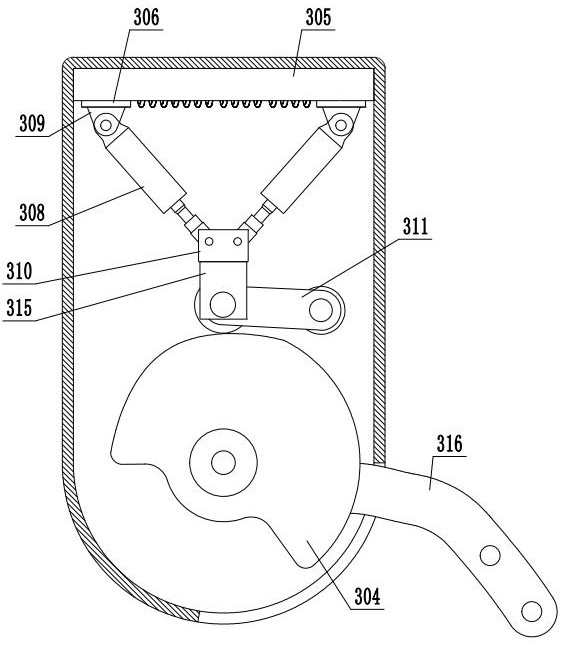
[0039] The present invention is specifically described below in conjunction with accompanying drawing, as Figure 1-12Shown: a waist-worn energy storage rehabilitation walker, comprising: a core support 1 installed on the waist; a waist belt 2 for fixing the core support 1 on the waist; an energy storage device 3 and the core support 1 Fixed connection; leg connector 4, one end is connected to energy storage device 3; strap 5, used to fix the other end of leg connector 4 on the leg; energy storage device 3 includes a housing 301, and the housing 301 is equipped with There are first rotating shaft 302, first bearing 303, cam 304, chute 305, slider 306, extension spring 307, push piece 308, first hinged seat 309, second hinged seat 310, chain plate 311, second The rotating shaft 312, the second bearing 313, the positioning shaft 314, the U-shaped piece 315 and the dial 316, the first rotating shaft 302 and the positioning shaft 314 are installed in the housing 301 in rotation, a...
PUM
Abstract
The invention discloses a waist-worn energy storage rehabilitation walker, which comprises a core support installed on the waist, a belt for fixing the core support on the waist, an energy storage device fixedly connected with the core support, and one end connected to the The leg connectors connected to the energy storage device, the straps used to fix the leg connectors on the legs, and the adjustment mechanism for adjusting the elastic force of the energy storage device. Shaft, first bearing, cam, chute, slide block, extension spring, push piece, chain plate, second rotating shaft, second bearing, positioning shaft, U-shaped piece and dial. The rehabilitation walker of the present invention is designed to be worn on the waist, which is easy to carry and wear, and has a small overall weight, which does not increase the patient’s walking load. The core support is installed on the waist, which is convenient for patients with incomplete upper limbs or injuries. , The energy storage device stores energy when standing, and provides assistance when the affected limb moves, which is convenient for patients to walk and can be used by patients of different weights and heights.
Description
technical field [0001] The invention relates to the field of medical walking equipment, in particular to a waist-worn energy storage rehabilitation walker. Background technique [0002] Rehabilitation medicine is a medical applied discipline that studies the rehabilitation of the disabled and patients. Its purpose is to make the sick and disabled get the maximum benefit as soon as possible through various means such as physical therapy, exercise therapy, life training, skill training, speech training and psychological counseling. Restoration to the maximum extent enables the functions of the remaining parts of the body to be brought into full play, to achieve the greatest possible self-care, labor and work abilities, and to lay the foundation for the reintegration of the sick and disabled into society. [0003] According to statistics, there are currently 8.77 million patients with limb dysfunction caused by stroke, spinal cord injury and various accidents in my country, and...
Claims
Application Information
Patent Timeline
Application Date:The date an application was filed.
Publication Date:The date a patent or application was officially published.
First Publication Date:The earliest publication date of a patent with the same application number.
Issue Date:Publication date of the patent grant document.
PCT Entry Date:The Entry date of PCT National Phase.
Estimated Expiry Date:The statutory expiry date of a patent right according to the Patent Law, and it is the longest term of protection that the patent right can achieve without the termination of the patent right due to other reasons(Term extension factor has been taken into account ).
Invalid Date:Actual expiry date is based on effective date or publication date of legal transaction data of invalid patent.