Energy-saving washing device for washing machine part processing

A technology for cleaning devices and parts, applied to heating devices, cleaning methods using liquids, dryers, etc. Ensure cleaning quality and improve drying efficiency

Active Publication Date: 2020-08-18
惠安县品创工业设计有限公司
View PDF10 Cites 5 Cited by
  • Summary
  • Abstract
  • Description
  • Claims
  • Application Information

AI Technical Summary

Problems solved by technology

[0006] Aiming at the deficiencies of the prior art, the present invention provides an energy-saving cleaning device for washing machine parts, which overcomes the deficiencies of the prior art, has a reasonable design and a compact structure, and aims to solve the problem of introducing medium and large The cleaning device is used to clean the workpiece, but its cost is high, the structure is complex and the energy consumption is high, which does not meet the problem of energy conservation advocacy

Method used


Image

  • Energy-saving washing device for washing machine part processing
  • Energy-saving washing device for washing machine part processing
  • Energy-saving washing device for washing machine part processing

Examples


Embodiment 1

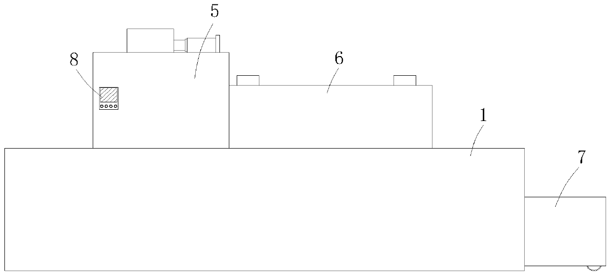
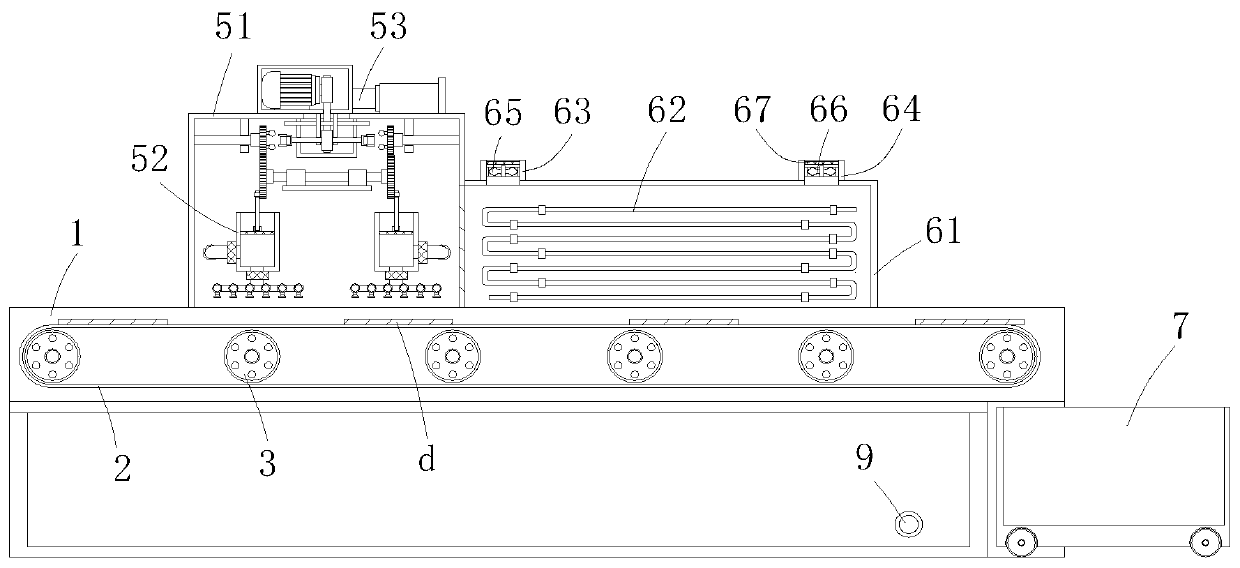
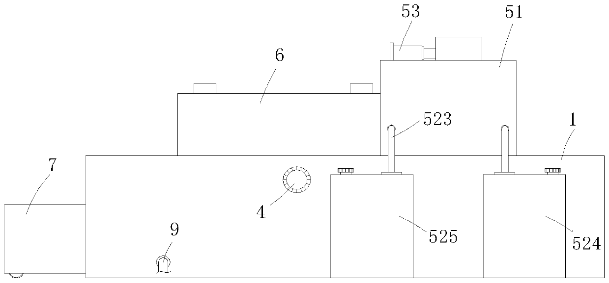
[0037] An energy-saving cleaning device for processing parts of a washing machine, comprising a strip-shaped transmission box 1 with an unclosed upper end, a transmission braided belt 2 for transporting a workpiece d is horizontally provided in the inner cavity of the strip-shaped transmission box 1, and the transmission braided There are a plurality of transmission wheels 3 rotating inside the belt 2, and the transmission wheels 3 are installed on the inside of the strip transmission box 1, and the rear axle end of one of the transmission wheels 3 extends to the outer cavity of the strip transmission box 1 and is installed in the strip transmission box 1. On the output end of the transmission motor 4, the transmission motor 4 is fixedly installed on the rear wall of the strip transmission box 1, the transmission motor 4 is started, and the transmission braid 2 is driven to transmit the workpiece d of the washing machine parts from left to right, and the strip transmission box ...

Embodiment 2

[0051] The difference between this embodiment and embodiment 1 is that, as Figure 1-3 As shown, the downstream of the cleaning mechanism 5 is provided with a drying mechanism 6, the drying mechanism 6 includes a drying chamber 61 erected on the upper end of the bar-shaped transmission box 1, and S-shaped The loop heating pipe network 62, and the two sides of the top wall of the drying chamber 61 corresponding to the conveying direction of the side panels are respectively provided with an air inlet 63 and an air outlet 64, and the air inlet 63 and the air outlet 64 are respectively provided with an air inlet 65 With exhaust fan 66, the upper end inboard of air inlet 63 and air outlet 64 is all equipped with filter screen.

[0052] In this embodiment, the S-shaped loop heating pipe network 63, the air intake fan 65 and the exhaust fan 66 are started synchronously, the air is taken in from above the workpiece d just cleaned, and the air is discharged from the top of the workpiec...


PUM


Abstract

The invention relates to the technical field of furniture processing equipment, and provides an energy-saving washing device for washing machine part processing, which aims to solve the problems thata medium-large-sized washing device introduced in an existing large-scale production plant is used for washing a workpiece, is higher in cost, is complex in structure, is high in operation energy consumption, and does not meet energy-saving proposal. The energy-saving washing device comprises a strip-shaped transmission box, upper end of which is not sealed, wherein a transmission braided strap for transmitting the workpiece is horizontally arranged in the inner cavity of the strip-shaped transmission box; a plurality of transmission wheels are rotatably arranged inside the transmission braided strap; the upper end of the strip-shaped transmission box is provided with a washing mechanism; the washing mechanism comprises a washing room arranged at the upper end of the strip-shaped transmission box, and a spraying-washing unit and a drive unit for driving the spraying-washing unit are arranged in the washing room. The energy-saving washing device is especially suitable for energy-savingefficient washing of washing machine parts, and has a higher social use value and a higher application prospect.

Description

technical field [0001] The invention relates to the technical field of home appliance processing equipment, in particular to an energy-saving cleaning device for washing machine parts. Background technique [0002] The washing machine is a cleaning appliance that uses electric energy to generate mechanical action to wash clothes. The washing machine is mainly composed of a cabinet, a washing and dehydrating bucket (some washing and dehydrating buckets are separated), a transmission and a control system, and some are also equipped with a heating device. [0003] After the parts inside the washing machine are processed and formed through multiple processes, a large amount of oil and processing debris often adhere to the surface of the workpiece, which cannot be directly used for assembly and needs to be cleaned. The traditional cleaning method is manual cleaning, which is a waste of labor and low cleaning efficiency, which does not meet the market demand. The existing large-sc...

Claims


Application Information

Patent Timeline
Patent Type & Authority Applications(China)
IPC IPC(8): B08B3/02B08B3/08B08B13/00F26B15/18F26B21/00F26B23/10F26B25/02
CPCB08B3/022B08B3/041B08B3/08B08B13/00F26B15/18F26B21/002F26B23/10F26B25/02
Inventor 谢秋玉王华辉
Owner 惠安县品创工业设计有限公司
Why Eureka
Try Eureka