
Mold with exhaust filter structure

A filter structure and mold technology, which is applied in the direction of manufacturing tools, mold handling equipment, casting molding equipment, etc., can solve problems such as unqualified molds, deviation of casting mold effects, large amounts of air bubbles and impurities in molds, etc., so as to avoid unqualified molds Effect

Pending Publication Date: 2020-08-18
合肥丰华汽车零部件有限公司
View PDF0 Cites 1 Cited by
  • Summary
  • Abstract
  • Description
  • Claims
  • Application Information

AI Technical Summary

Problems solved by technology

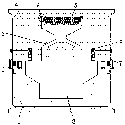
[0007] The purpose of the present invention is to provide a mold with an exhaust filter structure, to solve the phenomenon that the upper mold body and the lower mold body deviate from the ideal state caused by the deviation of the upper mold body and the lower mold body in the above-mentioned background technology, and the excessive impurities in the mold liquid cause the mold to be incomplete. Qualified phenomenon and the phenomenon that the produced mold contains a lot of bubbles and impurities

Method used


Image

  • Mold with exhaust filter structure
  • Mold with exhaust filter structure
  • Mold with exhaust filter structure

Examples


Embodiment Construction

[0024] The technical solutions in the embodiments of the present invention will be clearly and completely described below in conjunction with the accompanying drawings in the embodiments of the present invention. Obviously, the described embodiments are only some of the embodiments of the present invention, not all of them. In addition , the terms "first", "second", "third", "upper, lower, left, right", etc. are used for descriptive purposes only and should not be construed as indicating or implying relative importance. At the same time, in the description of the present invention, unless otherwise clearly stipulated and limited, the terms "connected" and "connected" should be understood in a broad sense, for example, it can be a fixed connection, a detachable connection, or an integral connection; It can be a mechanical connection or an electrical connection; it can be a direct connection or an indirect connection through an intermediary. Based on the embodiments of the presen...


PUM


Abstract

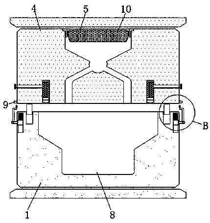
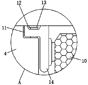
The invention discloses a mold with an exhaust filter structure. The mold includes a lower mold body, a moving plate, feed channels, a casting mold cavity, and a positioning groove. The lower mold body is internally provided with the casting mold cavity. An upper mold body is arranged above the lower mold body, fixed grooves at equal intervals are formed in the inner side of a feed inlet in the circumferential direction, and a placing groove is formed in the surface of one side of an L-shaped clamping plate. The feed channels are formed in the two sides of the inner part of the upper mold body, exhaust mechanisms are arranged on the two sides, above the casting mold cavity, of the inner part of the upper mold body, limiting baffles are fixed to the two sides of the bottom of the upper moldbody, adjusting grooves are formed in the two sides of the top of the lower mold body, and the side, away from the surfaces of the adjusting grooves, of a compression spring is fixedly connected witha fixing block. The clamping and positioning function at the time of installing the mold is realized, the function of filtering casting mold liquid by the mold is realized, and the function of discharging flue gas inside the mold is realized.

Description

technical field [0001] The invention relates to the field of mold technology, in particular to a mold with an exhaust filter structure. Background technique [0002] Casting mold means that in order to obtain the structural shape of the part, other easy-to-form materials are used to make the structural shape of the part in advance, and then the mold is placed in the sand mold, and then a fluid liquid is poured into the cavity of the net mold, and the liquid is cooled and solidified to form Parts with exactly the same shape and structure as the mold. [0003] There are many types of such casting molds on the market today, which can basically meet people's needs, but there are still some problems. The specific problems are as follows: [0004] 1. Traditional casting molds of this type are rarely equipped with snap-fit ​​positioning functions when installing casting molds, which can easily lead to deviations between the upper mold body and the lower mold body, resulting in the...

Claims


Application Information

Patent Timeline
IPC IPC(8): B22C9/00B22C9/08B22D33/00
CPCB22C9/00B22C9/086B22D33/00
Inventor 席跃坤席自强张英红张登柱金玉涛罗松王亮程金康侯学勇李秀东宋宇翔
Owner 合肥丰华汽车零部件有限公司
Learn More