Tie bar welding device

A welding device and tie rod technology, applied in auxiliary devices, welding equipment, auxiliary welding equipment, etc., can solve problems such as bolts cannot be connected smoothly, flange connection plates are easily dislocated, and cannot be guaranteed, and improve welding efficiency and welding quality. , The effect of ensuring force balance and reducing labor costs

Pending Publication Date: 2020-08-18
新疆福泰建设(集团)有限公司
View PDF0 Cites 0 Cited by
  • Summary
  • Abstract
  • Description
  • Claims
  • Application Information

AI Technical Summary

Problems solved by technology

The existing welding method cannot guarantee the above technical requirements, and at the same time, the bolt connection holes at both ends of the welded tie rod are not easy to measure
The flange connecting plates at both ends are easy to dislocate and tilt, and it is difficult to ensure that they are in the same plane and posit

Method used


Image

  • Tie bar welding device
  • Tie bar welding device
  • Tie bar welding device

Examples


Example Embodiment

[0026] The technical solutions in the embodiments of the present invention will be clearly and completely described below in conjunction with the accompanying drawings in the embodiments of the present invention. Obviously, the described embodiments are only a part of the embodiments of the present invention, rather than all the embodiments. Based on the embodiments of the present invention, all other embodiments obtained by those of ordinary skill in the art without creative work shall fall within the protection scope of the present invention.

[0027] In the description of the present invention, it should be understood that the terms "center", "longitudinal", "transverse", "length", "width", "thickness", "upper", "lower", "front", " "Back", "Left", "Right", "Vertical", "Horizontal", "Top", "Bottom", "Inner", "Outer", "Clockwise", "Counterclockwise" and other directions or The positional relationship is based on the position or positional relationship shown in the drawings, and ...


PUM


Abstract

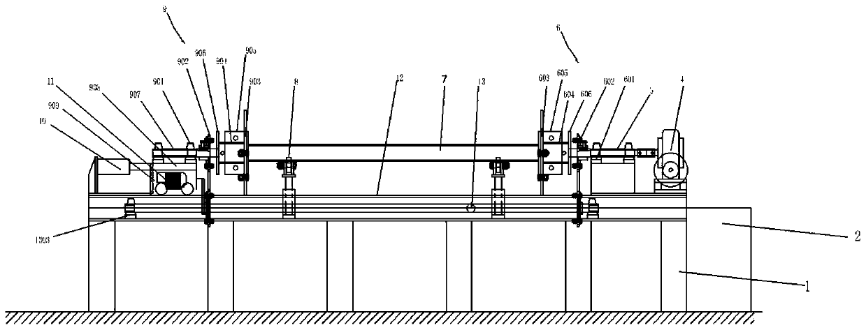
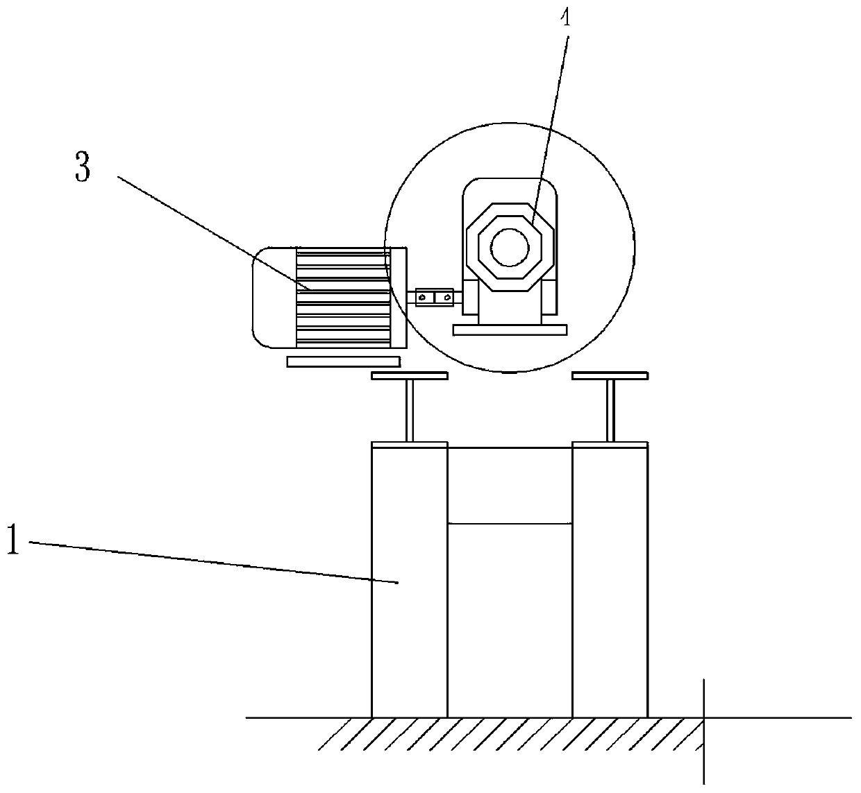
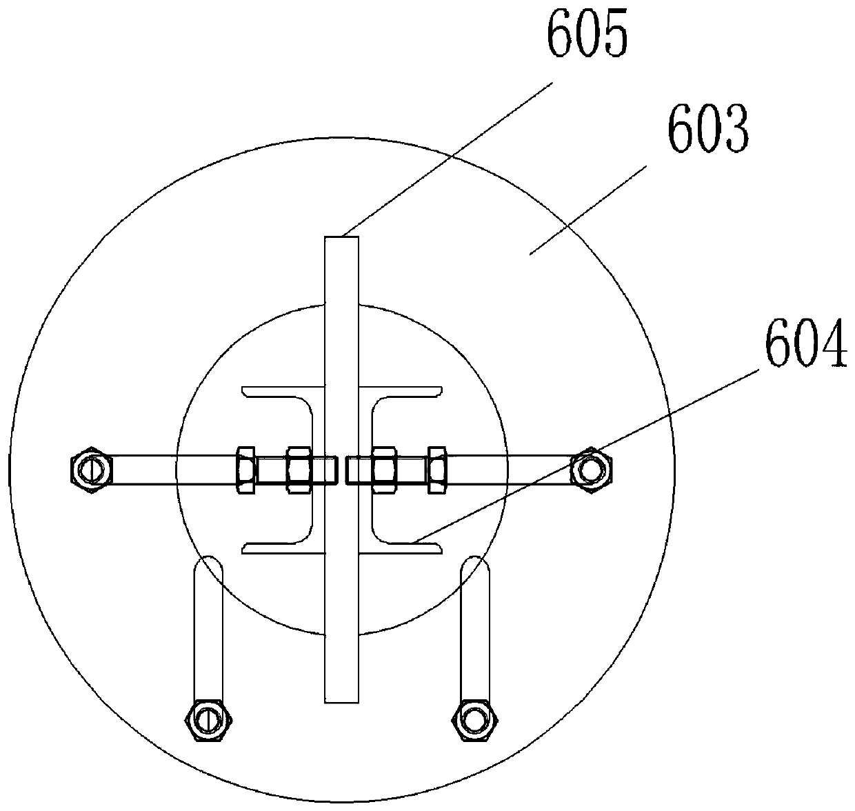
The invention relates to the technical field of building steel structure machining, in particular to a tie bar welding device. The tie bar welding device comprises an operation platform, an electric control box, a driving motor, a driving rotation mechanism, a tie bar, a tie bar pneumatic lifting support, a driven synchronous rotation mechanism and a hexagonal transmission shaft. Tie bar connecting plates A are arranged on the two sides of the tie bar, tie bar connecting plates B are fixed to a driving positioning disc and a driven positioning disc, and the movable side is pushed through a pneumatic pushing rod for clamping; the driving rotation mechanism and the driven synchronous rotation mechanism are arranged on the two sides of the tie bar correspondingly, the hexagonal transmission shaft is rotated to drive a driving chain wheel set and a driven chain wheel set, thus the driving rotation mechanism drives the tie bar and then drives the driven synchronous rotation mechanism to synchronously rotate, the tie bar pneumatic lifting support is arranged below the tie bar to ensure that center positions of different tie bars are stable, stress balance is ensured, the welding efficiency and the welding quality are improved, manual work is liberated, and the labor cost is lowered.

Description

technical field [0001] The invention relates to the technical field of building steel structure processing, in particular to a tie rod welding device. Background technique [0002] The welding of the existing tie rod is to rely on manual welding of one end to connect the flange plate. After welding one end, the other end is manually aligned and welded. It is necessary to ensure that the connecting plates on the flanges at both ends are on the same plane, and at the same time ensure that the connecting plates The location of the bolt holes. Existing welding methods cannot guarantee the above technical requirements, and the bolt connection holes at both ends of the welded tie rod are not easy to measure. The flange connecting plates at both ends are easy to dislocate and tilt, and it is difficult to ensure that they are in the same plane and position. When the finished tie rod is transported to the construction site, it is impossible to ensure that both ends are connected to ...

Claims


Application Information

Patent Timeline
IPC IPC(8): B23K37/00B23K37/047
CPCB23K37/00B23K37/047
Inventor 严威严竟李安平于航南何卫东
Owner 新疆福泰建设(集团)有限公司
Why Eureka
Try Eureka