Producing and machining process of high-speed rotor spindle
What is AI technical title?
AI technical title is built by Patsnap AI team. It summarizes the technical point description of the patent document.
A high-speed rotor and processing technology, applied in the field of rotor shafts, can solve problems such as scrapping, resource and cost loss, and achieve the effects of quality assurance, less equipment consumption, and reduced scrapping probability
Inactive Publication Date: 2020-08-18
南通捷越机电有限公司
View PDF6 Cites 0 Cited by
Summary
Abstract
Description
Claims
Application Information
AI Technical Summary
This helps you quickly interpret patents by identifying the three key elements:
Problems solved by technology
Method used
Benefits of technology
Problems solved by technology
[0004] The rotor shaft processing technology and the rotor shaft in the above patents have the following disadvantages: after the processing is completed, some rotor shafts whose center holes do not meet the requirements are directly scrapped because they cannot be adjusted and modified, resulting in loss of resources and costs
Method used
Image
Click on the blue label to locate the original text in one second.
Reading with bidirectional positioning of images and text.
Examples
Embodiment 1
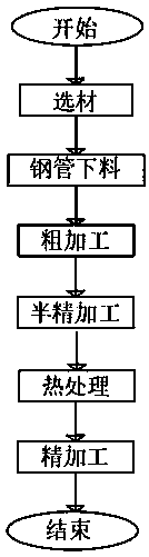
[0033] A production and processing technology of high-speed rotor shaft, such as figure 1 shown, including the following steps;
[0040] S7: After the processing is completed, its appearance and performance are inspected.
[0041] The S1 selects No. 45 steel whose size is Φ180mm*2530mm round steel material.
[0042] In the above S3, most of the margin on the steel is removed, so that the shape and size of the steel are close to the finished parts, and a center hole is punched on the end face of the steel. The outer circle of the car is Φ176mm-Φ177mm, and the taper is required to be no more than 0.5 0.05.
[0043] In the above S4, the main surface has a certain finishing allowance, and the reserved amount at both ends of the rotor shaft is 5-10mm.
[0044] The heat treatment steps in the S5 a...
Embodiment 2
[0052] A production and processing technology of high-speed rotor shaft, such as figure 1 Shown: Include the following steps.
[0059] S7: After the processing is completed, its appearance and performance are inspected.
[0060] The S1 selects No. 45 steel whose size is Φ180mm*2530mm round steel material.
[0061] In the above S3, most of the margin on the steel is removed, so that the shape and size of the steel are close to the finished parts, and a center hole is punched on the end face of the steel. The outer circle of the car is Φ176mm-Φ177mm, and the taper is required to be no more than 0.5 0.05.
[0062] In the above S4, the main surface has a certain finishing allowance, and the reserved amount at both ends of the rotor shaft is 5-10mm.
[0063] The heat treatment steps in the S5 are a...
PUM
Abstract
The invention discloses a producing and machining process of a high-speed rotor spindle, and relates to the technical field of rotor spindles. The process aims to solve the problem that after machining is completed, some central holes cannot meet the requirement, but no adjustment or modification can be made, so rejection is caused. The process specifically includes the following steps of S1, selecting materials; S2, discharging round steel; S3, performing rough machining; S4, performing semifinishing; S5, performing heat treatment; S6, performing finish machining; and S7, detecting the appearance and performance of the rotor spindle after machining is completed. The area of outer circles of two ends is added to a core shaft of the rotor spindle, so that the rigidity of the core shaft canbe improved as much as possible; a margin of about 5-10 mm is reserved at the two ends of the rotor spindle, so that secondary modification can be conveniently performed later according to machining requirements; and in actual operation, reserved parts are cut off directly during secondary modification and central holes are machined again, so that manpower waste and material resource waste which are caused by modification and maintenance of existing central holes are avoided, the rejection probability of the rotor spindle can be greatly reduced, and maintenance cost is reduced.
Description
technical field [0001] The invention relates to the technical field of rotor shafts, in particular to a production and processing technology for high-speed rotor shafts. Background technique [0002] The rotor shaft and body refer to forgings with sufficient mechanical strength, which can withstand the torque from the prime mover and the huge electromagnetic torque of sudden short-circuit at the generator outlet, and have good magnetic conductivity, and are the carrier of the main magnetic pole of the generator. , but the machining process of the rotor shaft is too complicated, and the quality of the rotor shaft processed by the processing method of the prior art is unstable, the repair rate is high, and the service life is short. Therefore, a high-speed rotor shaft production process is required. [0003] After retrieval, the Chinese Patent Publication No. CN110270796A discloses a machining process for the motor rotor shaft, including the following steps: Step 1, rough turn...
Claims
Application Information
Patent Timeline
Application Date:The date an application was filed.
Publication Date:The date a patent or application was officially published.
First Publication Date:The earliest publication date of a patent with the same application number.
Issue Date:Publication date of the patent grant document.
PCT Entry Date:The Entry date of PCT National Phase.
Estimated Expiry Date:The statutory expiry date of a patent right according to the Patent Law, and it is the longest term of protection that the patent right can achieve without the termination of the patent right due to other reasons(Term extension factor has been taken into account ).
Invalid Date:Actual expiry date is based on effective date or publication date of legal transaction data of invalid patent.

