

Vehicle power generation system and power generation control method
A power generation system and vehicle technology, applied in control devices, vehicle parts, transportation and packaging, etc., can solve problems such as not being able to meet the needs of high-power generators, and achieve the effect of meeting the needs of high-power generators
- Summary
- Abstract
- Description
- Claims
- Application Information
AI Technical Summary
Problems solved by technology
Method used
Image


Examples
Embodiment 1
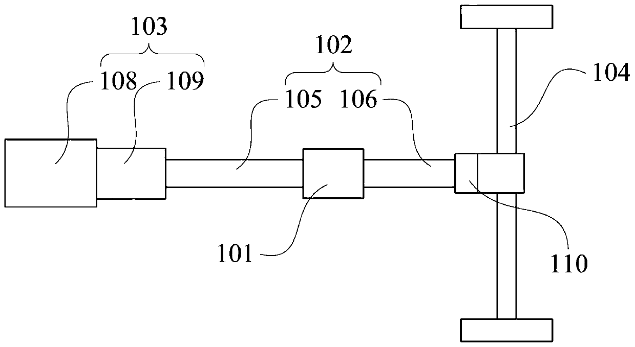
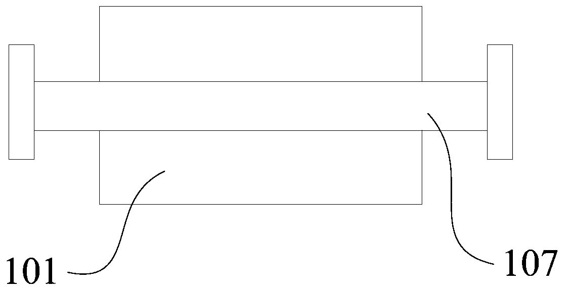
[0038] see Figure 1 to Figure 3 As shown, the vehicle power generation system provided by the present application includes a generator 101; the rotor of the generator 101 is connected to the transmission main shaft 102 of the vehicle, and the transmission main shaft 102 is used to connect the power plant 103 and the axle 104 of the vehicle.
[0039] Specifically, the power unit 103 of the vehicle is connected to the axle 104 through the transmission main shaft 102, thereby driving the wheels on the axle 104 to rotate, and realizing the driving function of the vehicle. In this application, the generator 101 is directly connected to the transmission main shaft 102 of the vehicle. Specifically, the transmission main shaft 102 rotates to drive the rotor of the generator 101 to rotate, so that the generator 101 realizes the power generation function.
[0040] The vehicle power generation system provided in this application is not limited by the power of the transmission power take...
Embodiment 2
[0049] The vehicle power generation system in the second embodiment is an improvement on the basis of the above embodiment. The technical content disclosed in the above embodiment will not be described repeatedly, and the content disclosed in the above embodiment also belongs to the content disclosed in the second embodiment.
[0050] see image 3 As shown, in the optional solution of this embodiment, the vehicle power generation system further includes a controller 111; the controller 111 is communicatively connected with the power unit 103 to control the power unit 103 to output a rated speed; the controller 111 and the control unit 112 of the generator A communication connection to connect or disconnect the stator magnetic circuit of the generator 101 .
[0051] In this embodiment, the controller 111 is specifically an ECU (Electronic Control Unit, electronic control unit), which has the functions of calculation and control. When the engine 108 is running, it can collect th...
Embodiment 3
[0056] Embodiment 3 of the present application provides a power generation control method, the method includes:
[0057] Receive the driving status information of the vehicle;
[0058] When the vehicle is in the driving state and the power generation demand information is received, the power disengagement device 110 is turned off, the engine 108 is controlled to output a rated speed, and the stator magnetic circuit connection of the generator 101 is controlled.
[0059] In this embodiment, when the vehicle is running and the generator 101 needs to work to output alternating current, the demand is transmitted through the control switch 114. At this time, the controller 111 responds to the demand, controls the engine 108 to output the rated speed, and transmits the demand through the transmission 109 and the transmission. The main shaft 102 outputs power to the generator 101 . At this time, the control unit 112 of the generator responds to the demand at the same time, and the g...
PUM
 Abstract
Description
Claims
Application Information