
Herringbone frame in form of hinge support for hoisting steel beam by winch and method of herringbone frame

A technology of a herringbone frame and a hoist, which is applied in the field of herringbone frames, can solve the problems of force deformation, fracture, and easy deformation of the bracket, and achieve the effect of reducing the bending moment.

Inactive Publication Date: 2020-08-18
CHINA CONSTR EIGHT ENG DIV CORP LTD
View PDF10 Cites 0 Cited by
  • Summary
  • Abstract
  • Description
  • Claims
  • Application Information

AI Technical Summary

Problems solved by technology

[0003] The embodiment of the present invention provides a herringbone frame in the form of a hinge support for hoisting steel beams. By changing the material of the support, the fixing mechanism and the support adopt a hinged connection mode, and the support can rotate on the fixing mechanism. The second wire rope and the third wire rope pull the top of the bracket to avoid deformation and fracture of the bracket due to excessive force. The bracket adopts a hinged connection method to reduce the bending moment on the bracket and avoid excessive force on the support. Deformation and fracture, the whole structure is more stable, which solves the problem that the support of the lifting support support in the current hoisting method is very large, and it is easy to be deformed by force, and the support is easily deformed or even broken when the force is too large problems causing safety incidents

Method used


Image

  • Herringbone frame in form of hinge support for hoisting steel beam by winch and method of herringbone frame
  • Herringbone frame in form of hinge support for hoisting steel beam by winch and method of herringbone frame
  • Herringbone frame in form of hinge support for hoisting steel beam by winch and method of herringbone frame

Examples


Embodiment Construction

[0039] The following will clearly and completely describe the technical solutions in the embodiments of the present invention with reference to the accompanying drawings in the embodiments of the present invention. Obviously, the described embodiments are only some, not all, embodiments of the present invention.

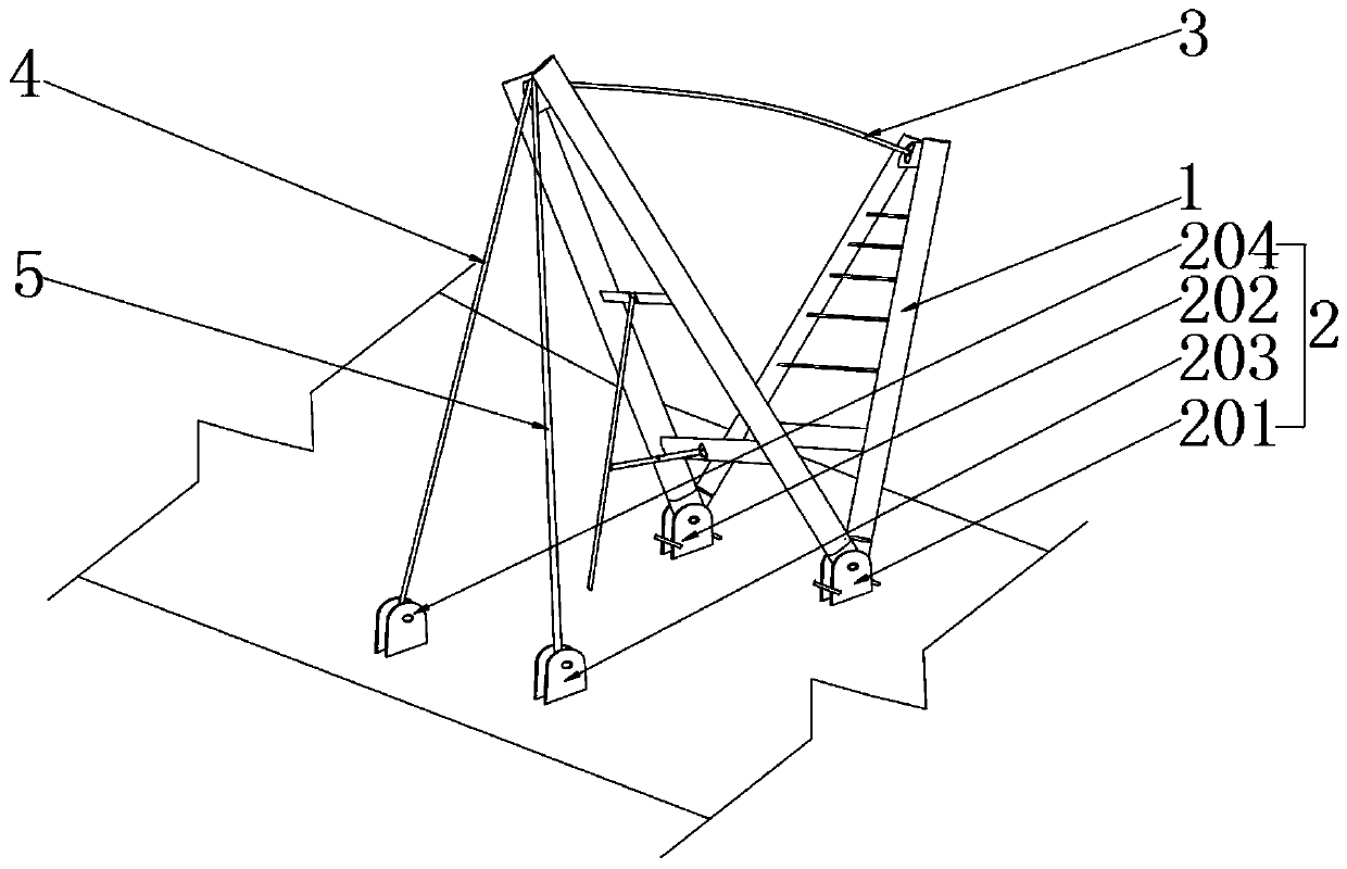
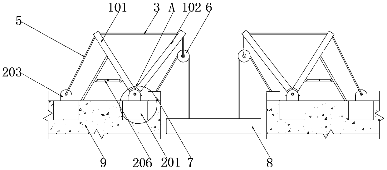
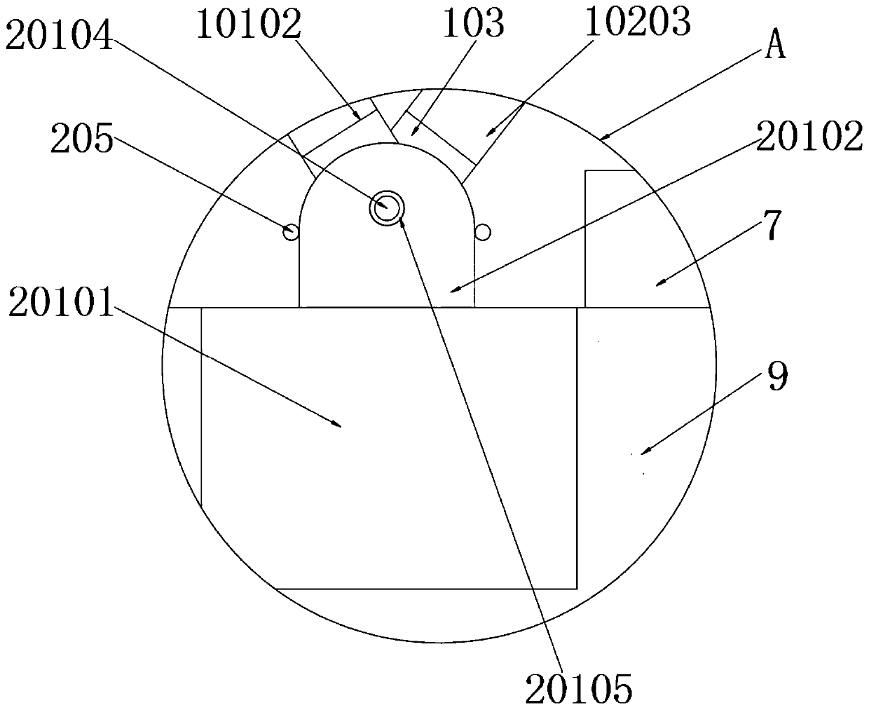
[0040] Refer to attached Figure 1-10 As shown, the support frame assembly 1, the support frame assembly 1 includes a first gable assembly 101, a second gable assembly 102, a connecting plate 103 and a limit plate 105, the first gable assembly 101 and The shape of the second gable assembly 102 is herringbone, the bottom of the first gable assembly 101 and the second gable assembly 102 are in contact with each other, the first fixing pipe 10101, the second fixing pipe 10101 The material of the pipe 10102, the third fixed pipe 10201, the fourth fixed pipe 10202, the first connecting pipe 10103, the second connecting pipe 10203, the first horizontal support pipe 10104 a...


PUM


Abstract

The invention provides a herringbone frame in the form of a hinge support for hoisting a steel beam by a winch and a method of the herringbone frame. The herringbone frame comprises a support frame assembly and a fixing mechanism, and a first herringbone frame assembly is respectively connected with a fourth fixing device and a third fixing device through a second steel wire rope and a third steelwire rope. According to the herringbone frame, when the steel beam is hoisted and installed, the support frame assembly is subjected to downward pulling force of the steel beam, and the support frameassembly can rotate around a first fixing device and a second fixing device, so that the situation that a support is prone to being deformed and fractured due to excessive stress is avoided; part ofthe pulling force of the steel beam to the support frame assembly is dispersed to the fourth fixing device and the third fixing device through the traction of the second steel wire rope and the thirdsteel wire rope, and the situation that the support frame assembly is deformed and fractured due to the fact that the weight of the steel beam is too large is avoided, so that the herringbone frame has the advantages that the bending moment at the support is reduced, the support is not prone to being deformed and fractured, and the support frame assembly is prevented from being deformed, bent andfractured due to excessive stress.

Description

technical field [0001] The invention relates to the technical field of construction equipment, in particular to a herringbone frame in the form of a hinge support used for hoisting steel beams and a method thereof. Background technique [0002] In the process of building construction, steel beams will be hoisted. The traditional hoisting method for steel beams is hoisting method. The hoisting bracket uses I-shaped steel as a bracket or uses I-shaped steel to make a herringbone bracket for lifting, and the I-shaped steel bracket is fixed. Installed on the top of the ring beam, a steel beam weighs close to 30 tons. When the I-beam bracket lifts the steel beam, the weight of the steel beam is all supported by the support as a whole. During the process of lifting the steel beam, the I-beam bracket The bending moment at the support is very large, and it is easy to deform under the force. In severe cases, it will be bent and broken, resulting in failure of hoisting. Moreover, the ...

Claims


Application Information

Patent Timeline
Patent Type & Authority Applications(China)
IPC IPC(8): E04G21/16B66C25/00
CPCB66C25/00E04G21/162
Inventor 张宁杨鑫缪万水
Owner CHINA CONSTR EIGHT ENG DIV CORP LTD
Learn More