
Method and system for purge control

A technology of controller and extraction valve, applied in electrical control, charging system, engine control, etc., can solve problems such as engine stall

Pending Publication Date: 2020-08-18
FORD GLOBAL TECH LLC
View PDF1 Cites 0 Cited by
  • Summary
  • Abstract
  • Description
  • Claims
  • Application Information

AI Technical Summary

Problems solved by technology

[0006] The inventors herein have realized that the problem of engine stalls due to initial canister rich conditions can be addressed by utilizing selective deactivation of engine cylinders

Method used


Image

  • Method and system for purge control
  • Method and system for purge control
  • Method and system for purge control

Examples


Embodiment Construction

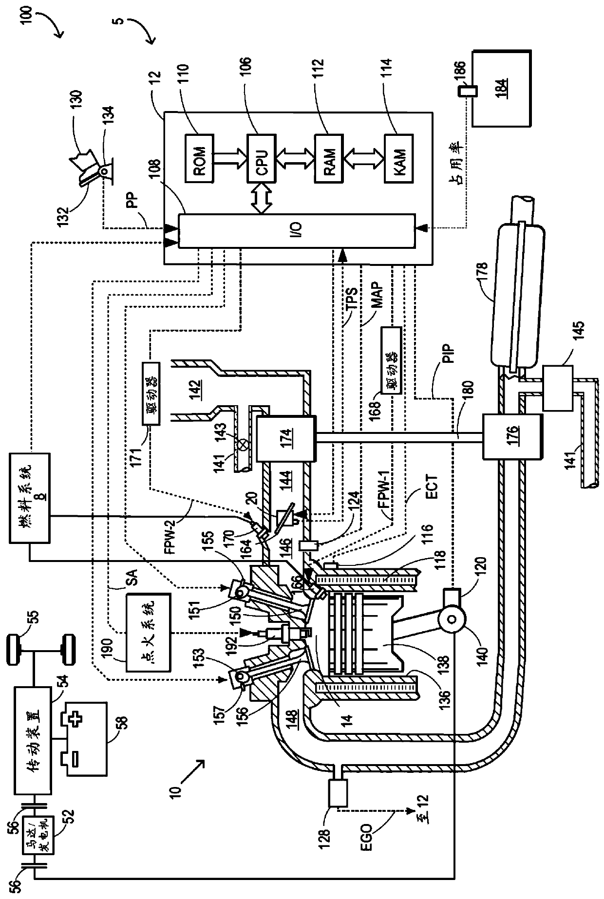
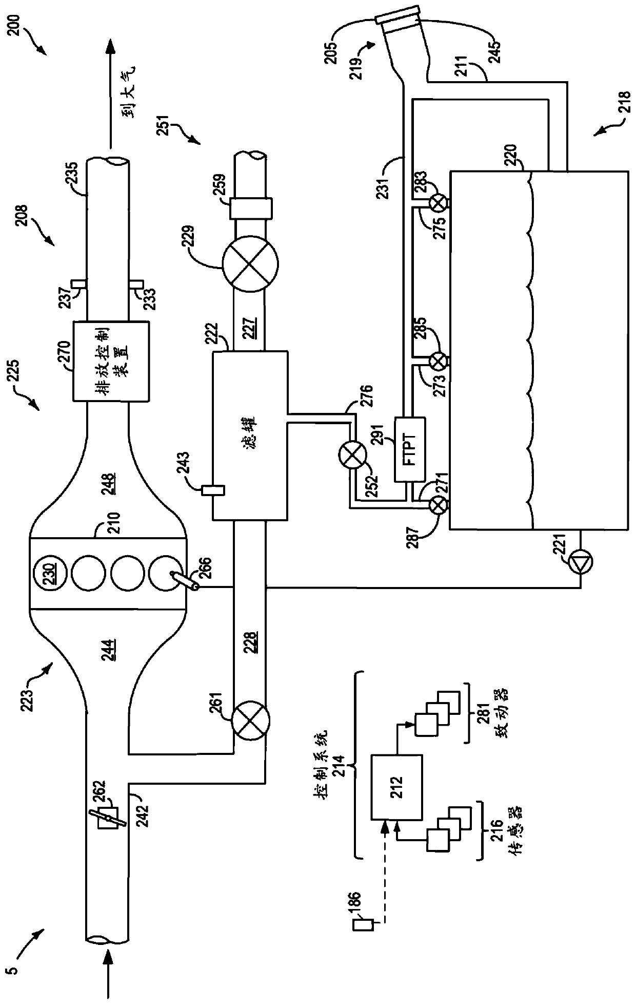
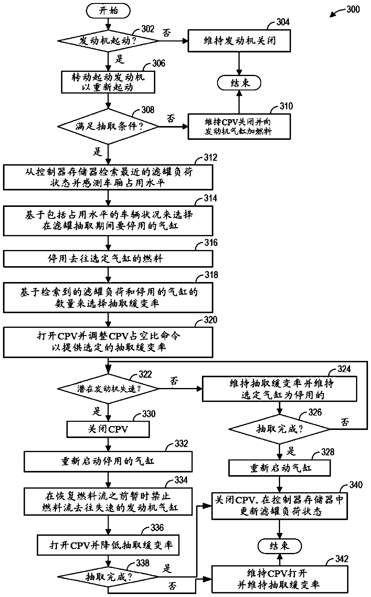
[0014] The following descriptions refer to methods used to reduce joins in figure 1 fuel system canisters in engine systems (such as in figure 2 Systems and methods for engine stall during purging of a fuel vapor recovery system). The controller can be configured to execute control routines such as image 3 An exemplary routine for purging a canister at a higher purge rate to an engine with one or more cylinders selectively deactivated. In response to an indication of a potential engine stall, deactivated cylinders may be reactivated and the purging rate may be reduced.

[0015] now turn figure 1 , illustrates an exemplary embodiment 100 of a combustion chamber or cylinder of an internal combustion engine 10 . Engine 10 may be coupled to a propulsion system, such as vehicle system 5 configured for on-road travel. Engine 10 may receive control parameters from a control system including controller 12 and input from a vehicle operator 130 via an input device 132 . In this ...


PUM


Abstract

The disclosure provides a method and a system for purge control. Methods and systems are provided for reducing engine stall incidence during canister purging. A fuel vapor canister is purged at a higher purge ramp rate to an engine with one or more cylinders selectively deactivated. In response to an indication of potential or partial engine stall, the deactivated cylinders are reactivated and thecanister purge ramp rate is lowered.

Description

technical field [0001] The present description generally relates to methods and systems for controlling a vehicle engine to reduce engine stall during fuel vapor canister purge. Background technique [0002] A vehicle fuel system may include a fuel vapor canister filled with an adsorbent for adsorbing fuel tank vapors. Adsorbed fuel tank vapors may include refueling vapors, diurnal vapors, and vapors released during fuel tank depressurization. Reduce fuel emissions by storing fuel vapors in the canister. Later, when the engine is in operation, the stored vapors may be purged into the engine intake manifold for use as fuel. The purging of fuel vapors may be ramped at a defined purging rate such that a target fuel vapor flow level is gradually reached. Slowly variable purging improves engine stability by reducing the likelihood of engine stall, which can occur if the canister being purged is loaded. [0003] Various methods have been developed to accelerate the release of ...

Claims


Application Information

Patent Timeline
Patent Type & Authority Applications(China)
IPC IPC(8): F02D17/02F02M25/08
CPCF02D17/02F02M25/08F02D41/0035F02D41/0045F02D41/0087F02D41/021F02D2200/50F02D2200/60F02D41/221
Inventor 艾德·杜道尔
Owner FORD GLOBAL TECH LLC
Learn More