Optical path system and laser radar

An optical path system and laser radar technology, applied in the field of detection, can solve the problems that the cost cannot be greatly reduced and mass production, 360° scanning cannot be achieved, and the technical parameter requirements of the first multi-emitter/receiver laser radar cannot be met.

Pending Publication Date: 2020-08-18
陈泽雄
View PDF1 Cites 1 Cited by
  • Summary
  • Abstract
  • Description
  • Claims
  • Application Information

AI Technical Summary

Problems solved by technology

However, the second type of solid-state lidar can only scan in one direction and cannot scan 360°. Multiple such solid-state radars must cooperate to achieve the effect of the first type of lidar, and only the first type of technology is relatively mature, so the cost cannot be greatly reduced. drop and mass production
[0005] Invention patent CN107153185A discloses a laser radar and a laser radar control method, which uses a vertical vibrating mirror and a horizontal rotating structure to complete three-dimensional scanning, and uses a transmitter to scan in the vertical direction through the vibrating mirror, replacing multiple tran

Method used


Image

  • Optical path system and laser radar
  • Optical path system and laser radar
  • Optical path system and laser radar

Examples


Embodiment Construction

[0028] This part will describe the specific embodiment of the present invention in detail, and the preferred embodiment of the present invention is shown in the accompanying drawings. Each technical feature and overall technical solution of the invention, but it should not be understood as a limitation on the protection scope of the present invention.

[0029] In the description of the present invention, it should be understood that the orientation descriptions, such as up, down, front, back, left, right, etc. indicated orientations or positional relationships are based on the orientations or positional relationships shown in the drawings, and are only In order to facilitate the description of the present invention and simplify the description, it does not indicate or imply that the device or element referred to must have a specific orientation, be constructed and operated in a specific orientation, and thus should not be construed as limiting the present invention.

[0030] I...


PUM


Abstract

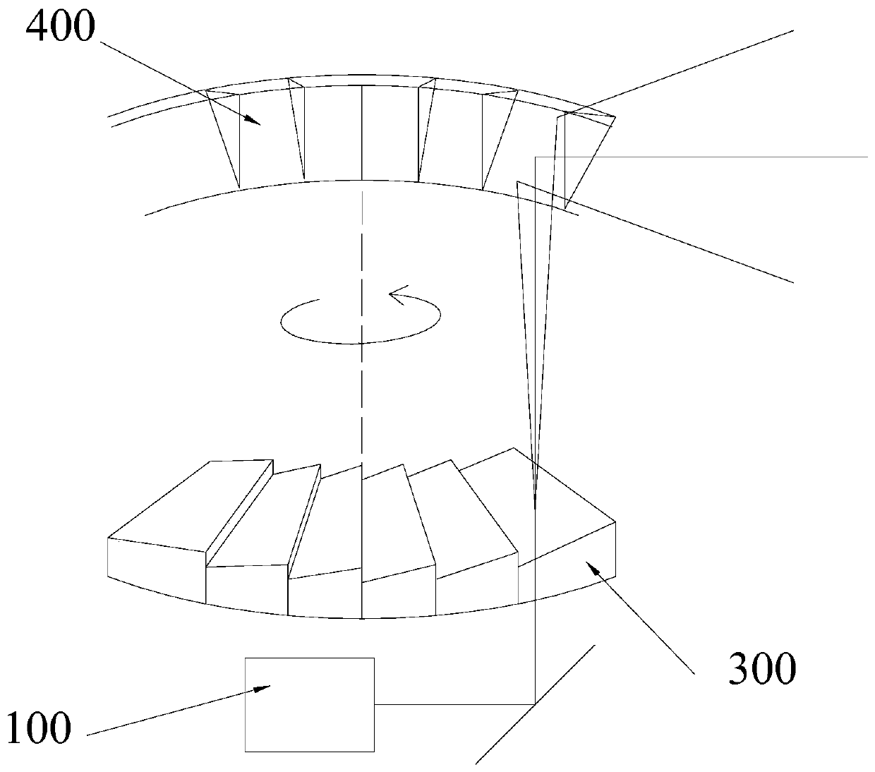
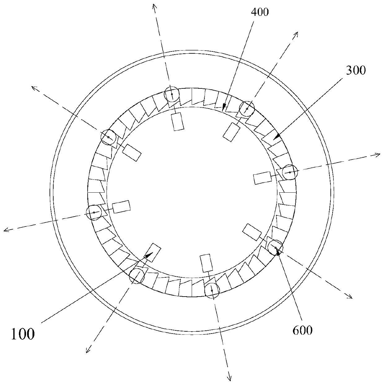
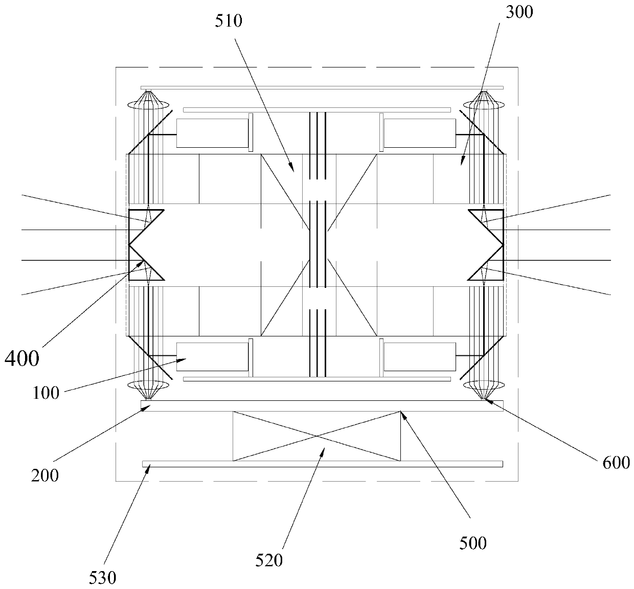
The invention discloses an optical path system and a laser radar. The optical path system is used for emitting N synchronous light rays into the rotary polyhedral prism; n scanning lights are formed by rotating the polyhedral prism; the scanning light is reflected by the fixed polyhedral prism to form N parts of vertical scanning light synchronously emitted from the circle center to the outer direction; compared with a single light source, the refreshing rate is improved by N times; when the refresh rate of 1/N is maintained, the scanning duration of each horizontal angle is correspondingly increased; the scanning time in the vertical direction in the horizontal scanning angle is prolonged; improving vertical resolution, laser radar, the device comprises N (at least two) laser transmitters, a optical path system, a horizontal rotating structure and a motor control module, laser emitted by the laser emitter emits N parts of vertical scanning light through the optical path system, the rotating speed can be reduced under the condition that the refresh rate is not changed, the scanning duration of each horizontal angle is increased, and therefore the vertical scanning time in the horizontal scanning angle is prolonged, and the resolution in the vertical direction is improved in a multiple-level mode.

Description

technical field [0001] The invention relates to the detection field, in particular to an optical path system and a laser radar. Background technique [0002] In fields such as autonomous driving, the higher the horizontal resolution, vertical resolution and refresh rate of lidar, the better the safety of autonomous driving. The laser radar in the prior art is mainly divided into two categories, the first category is a rotating multi-line laser radar, and the second category is a non-rotating laser radar, that is, a solid-state laser radar. [0003] The first type uses mechanical rotation to realize 3D scanning, which can meet the technical requirements of unmanned driving for 0.1° horizontal resolution (360°), 0.2-0.3° vertical resolution (up and down 15°) and 10-20 frame refresh rate, but The resolution in the vertical direction is proportional to the number of laser transmitters and receivers. For example, if you want to subdivide 128 parts in a 30° field of view in the v...

Claims


Application Information

Patent Timeline
IPC IPC(8): G01S7/481
CPCG01S7/4817
Inventor 陈泽雄
Owner 陈泽雄
Why Eureka
Try Eureka