Vibration signal calibration method, storage medium and electronic equipment

A vibration signal and calibration method technology, which is applied in the manufacture of motor generators, electric components, electromechanical devices, etc., can solve problems affecting tactile feedback and inconsistency of vibration feedback, and achieve the effect of enhancing tactile feedback and improving consistency

Active Publication Date: 2020-08-18
AAC TECH PTE LTD
View PDF5 Cites 3 Cited by
  • Summary
  • Abstract
  • Description
  • Claims
  • Application Information

AI Technical Summary

Problems solved by technology

[0004] In view of the above deficiencies in the prior art, the purpose of the present invention is to provide a vibration signal calibration method, storage medium and electronic equipment, aiming to solve the problem of inconsistent vibration feedback in the prior art during the batch use of motors, thereby Affected tactile feedback

Method used


Image

  • Vibration signal calibration method, storage medium and electronic equipment
  • Vibration signal calibration method, storage medium and electronic equipment
  • Vibration signal calibration method, storage medium and electronic equipment

Examples


Embodiment 1

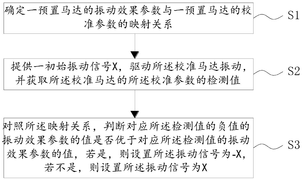
[0034] A method for calibrating a vibration signal proposed in this embodiment, the vibration signal is used to drive a calibration motor to vibrate, please refer to figure 1 , the adjustment method of the vibration signal includes:

[0035] S1. Determine a mapping relationship between a vibration effect parameter of a preset motor and a calibration parameter of a preset motor.

[0036] Specifically, the mapping relationship between the vibration effect parameters and the calibration parameters needs to be determined before subsequent calibration operations can be performed. Each parameter in the above step S1 is explained as follows:

[0037] The preset motor is a virtual motor model, which can be used to simulate an actual motor in some scenarios.

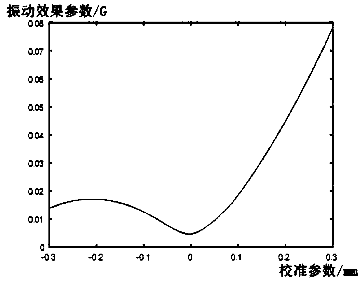
[0038] The vibration effect parameter is a parameter that reflects the vibration effect of the motor. More specifically, the vibration effect parameter is a parameter reflecting the vibration braking effect of the motor.

[0...

Embodiment 2

[0057] The computer-readable storage medium provided by this embodiment, the computer-readable storage medium stores a vibration signal calibration program, and when the vibration signal calibration program is run by a processor, the calibration of the vibration signal described in the above-mentioned embodiment 1 is performed method steps. For specific implementation, reference may be made to Method Embodiment 1, which will not be repeated here.

[0058] Also, see Image 6 , the present embodiment also provides an electronic device, the electronic device includes a processor 21, a memory 22 and a calibration program 23 for vibration signals, Image 6 Only some components of the electronic device are shown.

[0059] The storage 22 may be an internal storage unit of the electronic device in some embodiments, such as a hard disk or memory of the electronic device. The memory 22 may also be an external storage device of the electronic device in other embodiments, such as a plu...


PUM


Abstract

The invention provides a vibration signal calibration method, a storage medium and electronic equipment. The vibration signal calibration method comprises the following steps: firstly, determining a mapping relationship between a vibration effect parameter of a calibration motor and a calibration parameter thereof (the calibration parameter is a parameter reflecting a relationship between a structure parameter of the motor and a vibration displacement of the motor), so that after the initial vibration signal X drives the calibration motor, the detection value of the calibration parameter is obtained; and judging whether the value of the vibration effect parameter corresponding to the negative value of the detection value is superior to the value of the vibration effect parameter corresponding to the detection value in the mapping relation, if so, setting the initial vibration signal to be -X, and if not, setting the initial vibration signal to be X, thus enhancing tactile feedback of the calibration motor. Thus, in the batch use process of the motor, each motor monomer can carry out adaptive calibration on the vibration signal according to the structural parameters of the motor monomer, and the consistency of vibration feedback in the batch use process of the motor is improved, and tactile feedback is enhanced.

Description

【Technical field】 [0001] The invention relates to the technical field of linear motors, in particular to a vibration signal calibration method, storage medium and electronic equipment. 【Background technique】 [0002] In the application of electronic devices (smartphones or tablet computers, etc.), motors are playing an increasingly important role as tactile feedback. At present, in the production process of the motor, due to the influence of the magnetic circuit, structure, process and assembly, the motor will show a certain asymmetry. The specific performance is that the structural parameters of the motor will show asymmetry. More specifically It is manifested that the electromagnetic force, spring force, etc. are not symmetrical about the center point of the motor in terms of physical displacement. [0003] At present, in the mass use of motors, all motors are usually driven by fixed signals. It is unrealistic to design a dedicated signal for each motor unit to generate t...

Claims


Application Information

Patent Timeline
Patent Type & Authority Applications(China)
IPC IPC(8): G06F3/01H02K15/00G01H11/06G01B7/02G01B7/004
CPCG06F3/016H02K15/00G01B7/004G01B7/02G01H11/06G06F2203/014Y02T90/00
Inventor 郭璇向征谢兵
Owner AAC TECH PTE LTD
Why Eureka
Try Eureka