
Miniature transformer manufacturing method and miniature transformer

A technology of micro-transformer and manufacturing method, which is applied in the directions of transformer/inductor magnetic core, inductance/transformer/magnet manufacturing, transformer/inductor coil/winding/connection, etc. Connection, enameled wire waste and other problems, to achieve the effect of stable and reliable fixed connection, saving enameled wire, and simple process

Active Publication Date: 2020-08-18
ZHUHAI HAIWER ELECTRIC APPLIANCE CO LTD
View PDF5 Cites 0 Cited by
  • Summary
  • Abstract
  • Description
  • Claims
  • Application Information

AI Technical Summary

Problems solved by technology

Since the enameled wire wound around the hollow coil group is very thin, and the hollow coil group is also small, it is easy to tear off the wire end when binding and fixing the wire end on the terminal post, and the hollow coil group has multiple coil lead-out wires, which can be used in a small space. Fixing one coil lead wire may affect the connection between the other coil lead wire and the terminal, which is very inconvenient to operate
In addition, the length of the wire head of the coil lead-out wire will also affect the fixing of the coil lead-out wire and the terminal. If the wire head is too long, there will still be a long wire exposed after being fixed with the wiring, which may be overlapped to other terminals and affect the performance of the micro-transformer. Therefore, it needs to be cut off, resulting in a waste of enameled wire, and if the wire end is too short, it may make the coil lead-out wire not easy to fix with the terminal or easy to fall off, which will complicate the manufacturing process of the micro-transformer

Method used


Image

  • Miniature transformer manufacturing method and miniature transformer
  • Miniature transformer manufacturing method and miniature transformer
  • Miniature transformer manufacturing method and miniature transformer

Examples


Embodiment Construction

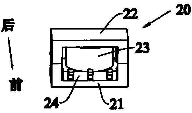
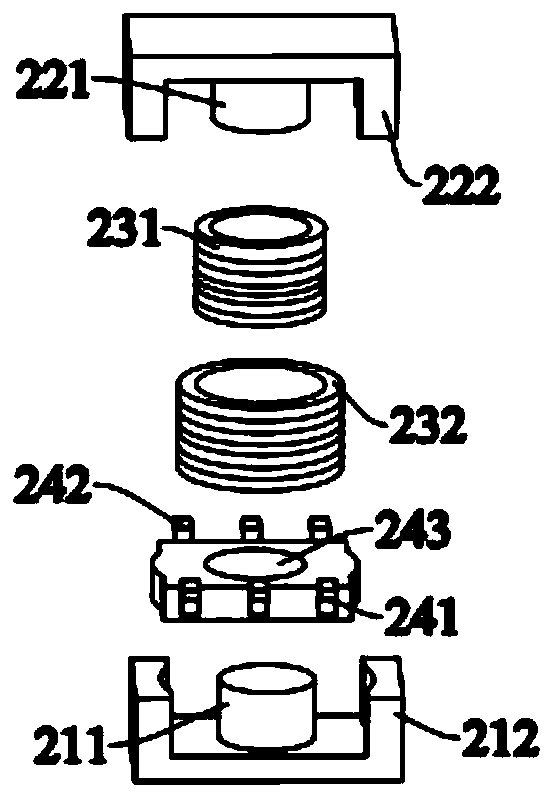
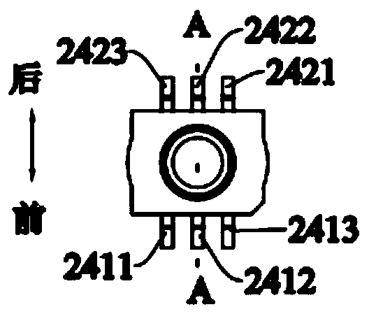
[0030] figure 1 and figure 2 A schematic structural view of an embodiment of the microtransformer of the present invention is shown. like figure 1 and figure 2 As shown, the microtransformer 20 includes a microtransformer including a first magnetic core 21, a second magnetic core 22, a first coil 231, a second coil 232, and a wiring base 24, wherein the first magnetic core includes a first outer peripheral portion 212 and a second magnetic core. A core part 211, the second magnetic core includes a second outer peripheral part 222 and a second core part 221, when the first magnetic core 21 and the second magnetic core 22 are installed together, the two ends of the first outer peripheral part 212 and the second Both ends of the outer peripheral portion 222 are in contact, the first outer peripheral portion 212 and the second outer peripheral portion 222 form a closed frame, and the first core portion 211 and the second core portion 221 are in contact to form a magnetic core...


PUM


Abstract

The invention provides a miniature transformer manufacturing method and a miniature transformer. The manufacturing method comprises the following steps: 1, providing a wiring base fixed with a wrapping post; 2, winding a first coil; 3, sequentially completing winding of other coils in the coil assembly; 4, removing the wrapping post; and 5, assembling a miniature transformer. When the coil is wound, the coil leading-out wire and the binding post of the wiring base are fixed together, so that the coil does not need to be fixed again after being wound, the operation is convenient, and the process is simple.

Description

technical field [0001] The invention relates to a manufacturing method of a miniature transformer and a miniature transformer manufactured by the method. Background technique [0002] A transformer is a device that uses the principle of electromagnetic induction to change the AC voltage. The main components include a coil group and a magnetic core. Micro-transformers are widely used. Micro-transformers are required in various mobile phone chargers, small electric tools, and other tiny electrical and electronic products. In the micro-transformer, the coil group is an essential and important part, and the quality of the coil has a great influence on the quality of the micro-transformer. The air-core coil group has the advantages of simple structure, high inductance precision, small distributed capacitance, high self-resonant frequency, small temperature coefficient, good stability, and strong anti-interference ability. [0003] Existing micro-transformers using hollow coil g...

Claims


Application Information

Patent Timeline
IPC IPC(8): H01F41/098H01F41/076H01F41/02H01F27/30H01F27/29H01F27/26
CPCH01F41/098H01F41/076H01F41/0206H01F27/306H01F27/29H01F27/263
Inventor 王亚东
Owner ZHUHAI HAIWER ELECTRIC APPLIANCE CO LTD
Learn More