Battery pack heat dissipation device and battery system

A heat dissipation device and battery pack technology, applied to battery pack components, secondary batteries, circuits, etc., can solve problems such as reduced battery life, untimely heat dissipation, battery impact, etc., to achieve faster efficiency, temperature balance, and safety high effect

Inactive Publication Date: 2020-08-18
GUANGDONG UNIV OF TECH
View PDF6 Cites 1 Cited by
  • Summary
  • Abstract
  • Description
  • Claims
  • Application Information

AI Technical Summary

Problems solved by technology

[0005] The present invention overcomes the problem of using the air-cooled heat dissipation system with the phase-change material for heat dissipation described in the above-mentioned background technology. Because the temperature of the battery varies greatly, sometimes when the temperature of the battery is too high, the phase-change material combined with air-cooled heat dissipation is not timely, which will damage the battery. cause a certain impact, reduce the service life of the battery, and also have certain safety risks; provide a battery pack cooling device and a battery system

Method used


Image

  • Battery pack heat dissipation device and battery system
  • Battery pack heat dissipation device and battery system
  • Battery pack heat dissipation device and battery system

Examples


Embodiment 1

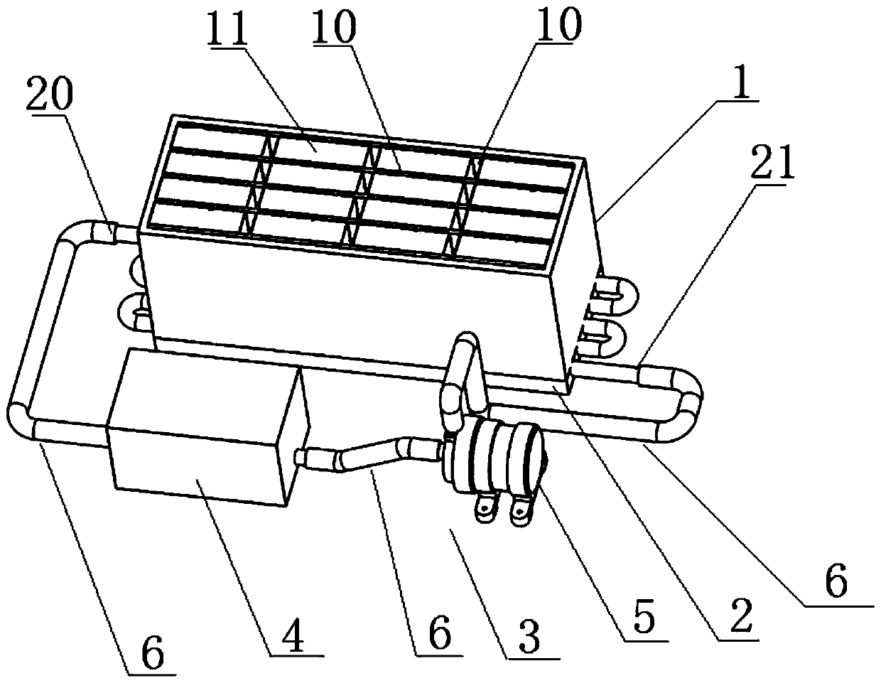
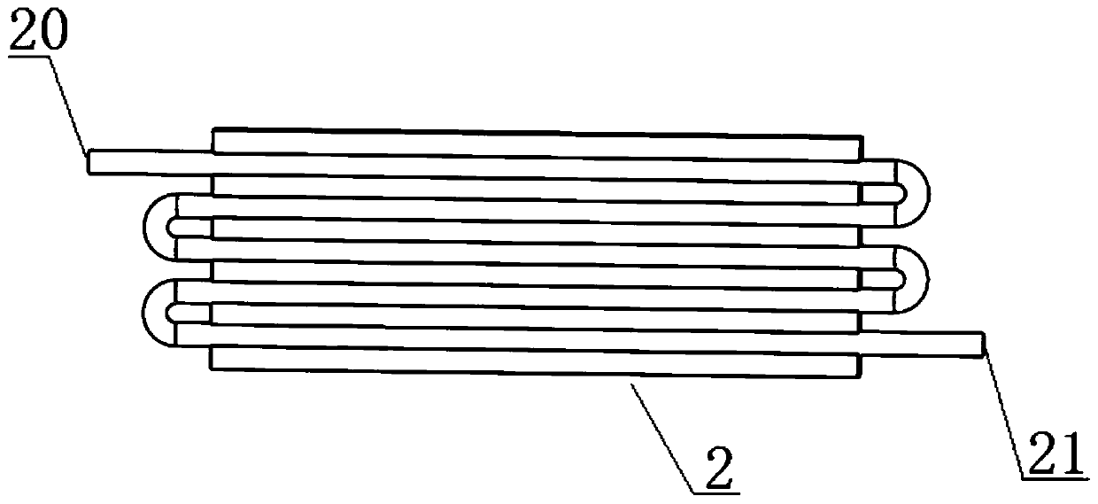
[0026] Such as figure 1As shown, it is a heat dissipation device for a battery pack, including a liquid cooling plate 2, a water circulation system 3, and a box 1 for placing a battery pack. The liquid cooling plate 2 is installed at the bottom of the box 1, and the water circulation One end of the system 3 is connected to the water inlet 21 of the liquid cooling plate 2 , and the other end is connected to the water outlet 20 of the liquid cooling plate 2 . The water circulation system 3 includes a water pump 5, a water tank 4 and a conduit 6. One end of the water tank 4 is connected to the water outlet 20 of the liquid cooling plate 2 through the conduit 6, and the other end is connected to the water inlet of the water pump 5 through the conduit 6. The water outlet end of the water pump 5 is connected to the water inlet 21 of the liquid cooling plate 2 through the conduit 6 . The water outlet 20 of the liquid cold plate 2 is provided with a temperature sensor, and the temper...

Embodiment 2

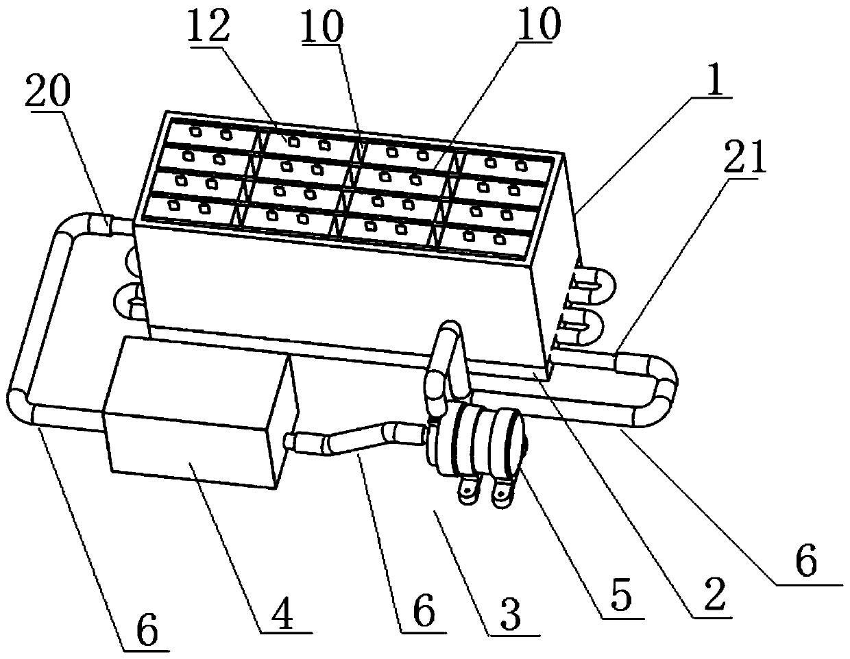
[0032] This embodiment provides a battery system, such as figure 2 As shown, including the lithium battery pack 12 and the battery pack cooling device provided in Embodiment 1, the lithium battery pack 12 is placed in the box body 1; each single battery in the lithium battery pack 12 is evenly installed in the battery placement groove of the box body 1 11, and reasonably connected, there is also a partition 10 between the battery and the outer wall of the casing 1 to separate. Combining the heat sink for the battery pack in Embodiment 1 with the battery pack forms a battery system that can be used. The battery system has high stability and is suitable for electric vehicles or electric motorcycles. Lithium battery 12 is a good rechargeable and dischargeable battery with high stability and long service life, and it has better effect when used in this battery system.


PUM

PropertyMeasurementUnit
thicknessaaaaaaaaaa
thicknessaaaaaaaaaa

Abstract

The invention provides a battery pack heat dissipation device which comprises a liquid cooling plate, a water circulation system and a box body for placing a battery pack. The liquid cooling plate isarranged at the bottom of the box body, one end of the water circulation system is connected with a water inlet of the liquid cooling plate, and the other end of the water circulation system is connected with a water outlet of the liquid cooling plate. The present invention further provides a battery system which is characterized by comprising the battery pack heat dissipation device, wherein thebattery pack is placed in the box body. According to the invention, the water circulation system is combined with the liquid cooling plate for heat dissipation, so that the efficiency of dissipating heat to the outside is greatly improved; the opening and closing of the water circulation system can be adjusted according to the use state, when the temperature of the battery pack is too high, the water circulation system is turned on, the higher the temperature is, the higher the working power of the water circulation system is, and the outward transportation and dissipation of heat are accelerated; and the liquid cooling plate is located on the box surface of the highest temperature position of the battery pack box body, so that the heat dissipation efficiency is greatly improved.

Description

technical field [0001] The present invention relates to the technical field of battery heat dissipation, and more specifically, to a heat dissipation device for a battery pack and a battery system. Background technique [0002] As a new generation of transportation, new energy electric vehicles have incomparable advantages over traditional vehicles in terms of energy saving, emission reduction, and reduction of human dependence on traditional fossil energy. [0003] As the core component of new energy electric vehicles, batteries can be operated safely and reliably. On the one hand, when the electric vehicle is just starting and climbing a hill, or during charging and discharging, the battery will emit a lot of heat. If the heat cannot be dissipated quickly, it will cause thermal runaway of the battery, and in severe cases, the battery may be in danger of violent expansion and explosion. On the other hand, when electric vehicles are driving on rough roads, there will be fr...

Claims


Application Information

Patent Timeline
Patent Type & Authority Applications(China)
IPC IPC(8): H01M10/613H01M10/625H01M10/6554H01M10/6556H01M10/6568H01M10/635H01M10/617H01M10/653H01M10/659H01M2/10H01M50/249
CPCH01M10/613H01M10/625H01M10/6554H01M10/6556H01M10/6568H01M10/635H01M10/617H01M10/653H01M10/659H01M50/20Y02E60/10
Inventor 莫崇茂杨晓青吴锡鸿黄泳瀚程东波黄润业王宇王奕淋
Owner GUANGDONG UNIV OF TECH
Why Eureka
Try Eureka