Rapid powder stirring device for interior decoration

A technology of stirring device and interior decoration, which is applied in the directions of mixer accessories, transportation and packaging, dissolving, etc., can solve the problems of waste of powder and inability to clean the stirring device, and achieve the effect of convenient use, convenient stirring and mixing treatment, and reducing waste.

Inactive Publication Date: 2020-08-21
闫顺
View PDF1 Cites 2 Cited by
  • Summary
  • Abstract
  • Description
  • Claims
  • Application Information

AI Technical Summary

Problems solved by technology

[0003] The currently announced Chinese patent authorization announcement number is CN110975737U, a kind of building decoration mixing device for painting raw materials. Although the powder can be

Method used


Image

  • Rapid powder stirring device for interior decoration
  • Rapid powder stirring device for interior decoration
  • Rapid powder stirring device for interior decoration

Examples


Embodiment 1

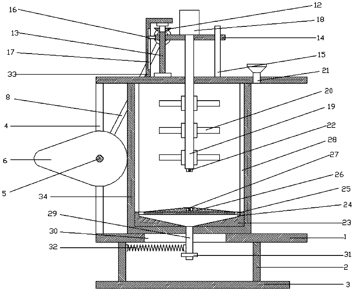
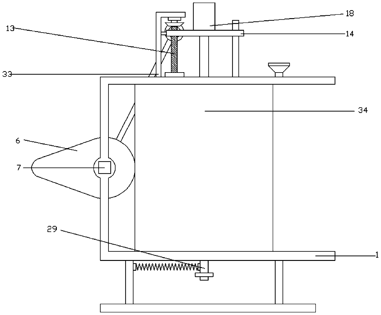
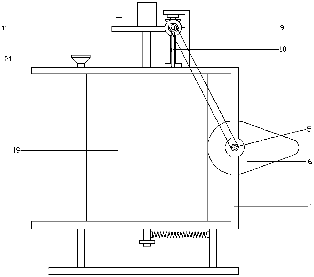
[0026] refer to Figure 1~4 , in an embodiment of the present invention, a powder rapid mixing device for interior decoration, comprising a connecting frame 1, a supporting plate 2 is fixedly installed at the left and right ends of the lower side of the connecting frame 1, and a bottom plate 3 is installed on the lower side of the supporting plate 2, The whole device can be effectively supported, so as to ensure the stability of the device. The first opening 4 is provided on the left side wall of the connecting frame 1, and the first opening 4 is connected with the cam 6 through the rotating shaft 5, and the driving motor is installed on the front side of the rotating shaft 5 7. The driving motor 7 is installed on the front side wall of the connection frame 1, and the rotating shaft 5 is driven to rotate through the driving motor 7, and the rotating shaft 5 will drive the cam 6 to rotate, which can facilitate the movement of the driving device.

[0027] The rotating shaft 5 po...

Embodiment 2

[0031] The difference from Embodiment 1 is that a limit rod 15 is installed on the right end of the connecting plate 14, the lower side of the limit rod 15 is connected with the connection frame 1, a limit block 16 is installed on the left side of the connection plate 14, and the left end of the limit block 16 is inserted into the limit In the position groove 17, the limit groove 17 is arranged on the fixed frame 33, and through the setting of the limit rod 15, the limit block 16 and the limit groove 17, the connecting plate 14 can be effectively limited, so that the connection can be ensured. The plate 14 makes a steady up and down movement.


PUM


Abstract

The invention relates to a large range, and especially relates to a rapid powder stirring device for interior decoration. The device comprises a connecting frame, a first opening is formed in the leftside wall of the connecting frame, the first opening is connected with a cam through a rotating shaft, the rotating shaft is connected with a connecting rod through a belt, a first helical gear is arranged on the front side of the connecting rod, the upper side of the first helical gear is engaged with a second helical gear, the second helical gear is mounted at the upper end of a threaded rod, the threaded rod is in threaded connection with a connecting plate, a stirring motor is mounted in the middle of the connecting plate, a stirring shaft is arranged below the stirring motor, a stirringrod is mounted on the stirring shaft, a connecting seat is mounted at the bottom of a stirring cylinder, a flow guiding tank is arranged in the connecting seat, material discharging ports are arrangedin four corners of the upper end of the flow guiding tank, and scraping plates are arranged at the left end and the right end of the upper side of the connecting seat. The stirring efficiency of thedevice can be effectively improved, the cleaning of the inner wall of the device is convenient, the powder waste is reduced, and the use of the device is convenient.

Description

technical field [0001] The invention relates to a relatively large range, in particular to a fast mixing device for powder materials used in interior decoration. Background technique [0002] Interior decoration is a concept including room design, decoration, furniture arrangement and various small decorations. It focuses on the decoration and construction inside the building, not only during the decoration design and construction period, but also includes long-term continuous decoration after living in. Decoration and decoration are Inseparable, in the process of interior decoration, it is often necessary to paint the wall, so that the powder stirring device will be used to stir and mix the powder into a uniform solution. [0003] The currently announced Chinese patent authorization announcement number is CN110975737U, a kind of building decoration mixing device for painting raw materials. Although the powder can be stirred and mixed, the equipment cannot clean the inner wa...

Claims


Application Information

Patent Timeline
IPC IPC(8): B01F11/00B01F15/00
CPCB01F31/24B01F31/56B01F35/123B01F35/31B01F35/3204
Inventor 闫顺
Owner 闫顺
Why Eureka
Try Eureka