
High polymer coating backflow protection device capable of automatically working based on flowing direction

A backflow protection, automatic working technology, applied in liquid filling, barrel/barrel filling, etc., can solve the problems of waste, paint overflow, slow filling of paint barrels, etc., to achieve the effect of simple structure and convenient use

Active Publication Date: 2020-08-21
抚州中和科技有限公司
View PDF4 Cites 0 Cited by
  • Summary
  • Abstract
  • Description
  • Claims
  • Application Information

AI Technical Summary

Problems solved by technology

[0003] Polymer water-based paints are generally stored in barrels. During the production, packaging and actual use, the paints are often loaded into barrels, and the produced paints are delivered to individual paint barrels through the feeding tube. Internally, when filling the bucket, if the staff does not pay attention to observation, or the transmission of the paint bucket fails, causing a single paint bucket to stay under the feeding pipe for too long, it will cause the filling of the paint bucket to be too slow, and the paint will flow backwards. Bucket overflows, causing waste

Method used


Image

  • High polymer coating backflow protection device capable of automatically working based on flowing direction
  • High polymer coating backflow protection device capable of automatically working based on flowing direction
  • High polymer coating backflow protection device capable of automatically working based on flowing direction

Examples


Embodiment Construction

[0022] The following will clearly and completely describe the technical solutions in the embodiments of the present invention with reference to the accompanying drawings in the embodiments of the present invention. Obviously, the described embodiments are only some, not all, embodiments of the present invention. Based on the embodiments of the present invention, all other embodiments obtained by persons of ordinary skill in the art without making creative efforts belong to the protection scope of the present invention.

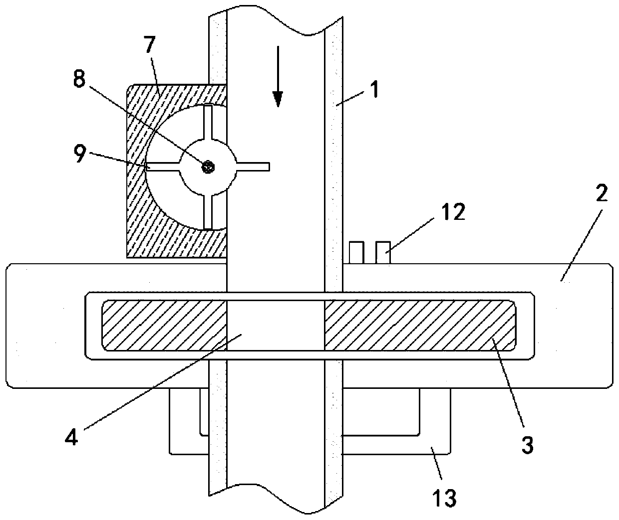
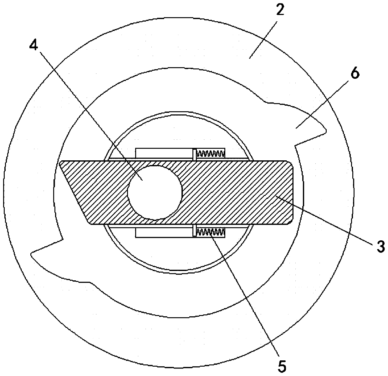
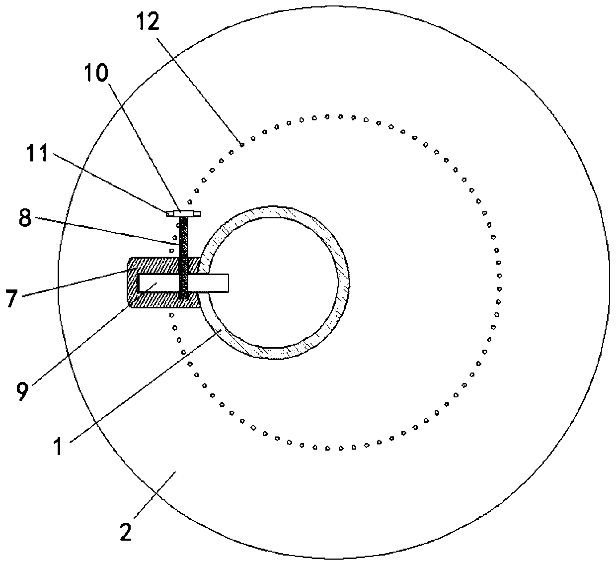
[0023] see Figure 1-4 , a polymer paint backflow protection device based on the automatic operation of the flow direction, including a feeding tube 1, a base 13 is fixedly sleeved on the outside of the feeding tube 1, and a movable joint is connected to the top of the base 13 and is located on the outside of the feeding tube 1. Seat 2, the inside of the movable seat 2 is movably plugged with a blocking plate 3 that runs through the blanking pipe 1, and the in...


PUM


Abstract

The invention provides a high polymer coating backflow protection device capable of automatically working based on the flowing direction. The device comprises a discharging pipe. The top of the base is rotationally connected with a moving seat. A blocking plate is movably connected in the moving seat in an inserted manner, and a through hole is formed in the blocking plate. The outer side of a rotating shaft is movably connected with an impeller in a sleeved manner. The back face of the rotating shaft is fixedly connected with a rotating disc. Evenly-distributed driving levers are arranged onthe ring side wall of the rotating disc. The top of the moving seat is fixedly connected with cylinders corresponding to the driving levers. When backflow happens in the discharging pipe, coating wells up to drive the impeller to rotate anticlockwise, the impeller drives the rotating shaft and the rotating disc to rotate, the rotating disc drives the moving seat to rotate through the driving levers and the cylinders, and therefore the moving seat rotates anticlockwise; and when a groove in a clamping groove is aligned to a slope segment on the blocking plate, the blocking plate shifts, the through hole and the discharging pipe are staggered to block the discharging pipe, coating is prevented from continuing to flow out, and the problem that when backflow happens to the discharging pipe, discharging continues, and consequently coating is wasted is effectively solved.

Description

technical field [0001] The invention relates to the technical field of polymer coatings, in particular to a backflow protection device for polymer coatings that works automatically based on flow direction. Background technique [0002] Polymer coatings are mainly divided into solvent-based coatings and water-based coatings. Water-based coatings use water as a solvent and are in an amorphous liquid state at room temperature. After being applied, they can form substances with certain thickness and waterproof functions on the surface of the structure. Water-based coatings are widely used in the construction field due to their non-flammable, non-polluting, waterproof and breathable functions. [0003] Polymer water-based paints are generally stored in barrels. During the production, packaging and actual use, the paints are often loaded into barrels, and the produced paints are delivered to individual paint barrels through the feeding tube. Internally, when filling the bucket, i...

Claims


Application Information

Patent Timeline
IPC IPC(8): B67C3/30
CPCB67C3/30
Inventor 管彦传
Owner 抚州中和科技有限公司
Learn More