Laying method of blast-furnace bottom for guiding furnace bottom to be in shape of pot bottom

A blast furnace and masonry technology, applied in blast furnace, blast furnace details, blast furnace parts and other directions, can solve problems such as business difficulties, carbon brick erosion, economic losses, etc., to achieve fast construction, prolong furnace service life, and improve construction speed. Effect

Inactive Publication Date: 2020-08-21
ANGANG STEEL CO LTD
View PDF4 Cites 1 Cited by
  • Summary
  • Abstract
  • Description
  • Claims
  • Application Information

AI Technical Summary

Problems solved by technology

Since 2003, our country has been greater than 2000m 3 Hearth burn-through accidents have occurred in more than 10 large blast furnaces, some of which even occurred in the early stages of furnace operation. Hearth burn-through accidents have caused great difficulties and huge economic losses to business operations
After the damage investigation, it is believed that because the bottom of the furnace has an "inverted pot bottom" or "flat" shape, within the range of 100mm to 200mm from the upper edge of the ceramic pad on the bottom of the furnace, there is always a layer of molten or semi-molten molten iron stored. Since the molten iron in this state has almost no fluidity, the molten iron circulates mainly along the hearth side wall during the tapping process of the blast furnace. Therefore, the erosion of carbon bricks in the range of 200mm from the upper edge of the furnace bottom ceramic pad to 1000mm below the center line of the taphole is aggravated.

Method used


Image

  • Laying method of blast-furnace bottom for guiding furnace bottom to be in shape of pot bottom

Examples


Embodiment Construction

[0017] The specific embodiment of the present invention is further described below in conjunction with accompanying drawing:

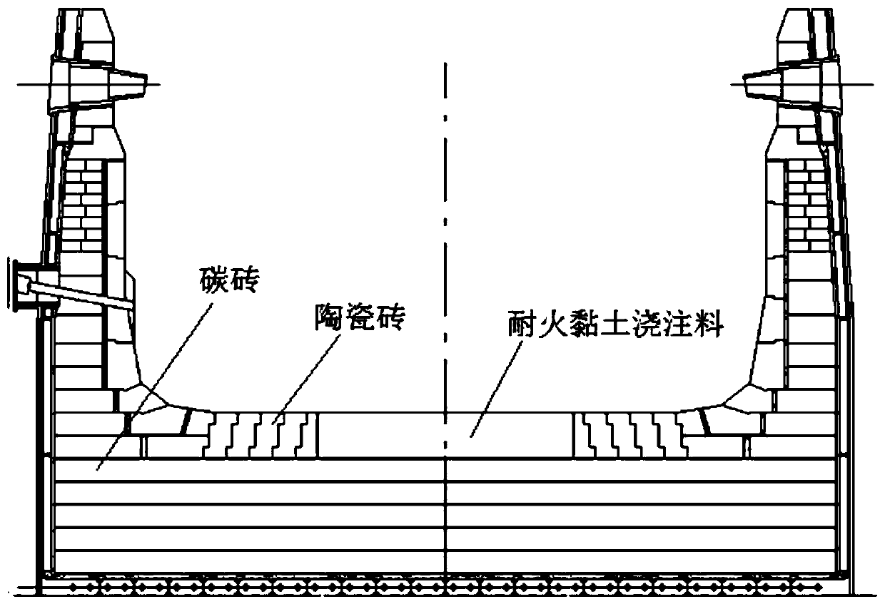
[0018] like figure 1

[0019] A blast furnace bottom masonry method for guiding the furnace bottom into a pot bottom shape, comprising the following steps:

[0020] 1) When building the ceramic brick layer at the bottom of the furnace, leave a circular groove with a diameter of 3750-4200mm in the center of the ceramic brick layer at the bottom of the furnace;

[0021] 2) Arrange the mold in the circular groove, and pour the refractory clay pouring material in the mold. There is a gap of 10 mm to 12 mm between the cast body and the surrounding ceramic bricks after pouring. The upper surface of the cast body is level with the ceramic bricks, and the height error between the two <2mm;

[0022] 3) Fill the gap with ceramic bulk material and compact it, requiring a compression rate of not less than 40%;

[0023] 4) After the pouring construction is comp...


PUM

PropertyMeasurementUnit
diameteraaaaaaaaaa

Abstract

The invention relates to a laying method of a blast-furnace bottom for guiding the furnace bottom to be in the shape of pot bottom. Ceramic bricks are not laid in the center of a furnace bottom ceramic brick layer, a refractory clay pouring material is adopted for pouring, after a blast furnace is put into operation, the refractory clay pouring material in the center of the furnace bottom is gradually eroded by molten iron, and thus the furnace bottom is in the shape of pot bottom. According to the laying method, the ceramic bricks are not laid in the center of the furnace bottom ceramic bricklayer, the refractory clay pouring material is adopted for pouring, the characteristic of poor molten iron erosion resistance of the clay material is used, the pot bottom is gradually eroded and formed after 6-9 months of blast furnace operation, then the whole furnace bottom gradually forms a 'pot bottom' shape, the service life of the first generation of the blast furnace can be effectively prolonged, meanwhile because the clay pouring material is low is price and fast in construction, the investment is saved, and the construction speed is increased.

Description

technical field [0001] The invention relates to a blast furnace construction method, in particular to a blast furnace bottom masonry method for guiding the bottom of the blast furnace into a pot bottom shape. Background technique [0002] In iron and steel enterprises, blast furnace ironmaking costs and energy consumption account for more than 70% of joint enterprises. The main problems of blast furnaces are smooth running and longevity, and longevity is the key to the sustainable development of ironmaking. Since 2003, our country has been greater than 2000m 3 Hearth burn-through accidents occurred in more than 10 large-scale blast furnaces, some of which even occurred in the early stage of furnace service. Hearth burn-through accidents caused great difficulties and huge economic losses to business operations. At present, there are still a large number of large-scale blast furnaces that have potential safety hazards. The blast furnaces are forced to take measures to reduce...

Claims


Application Information

Patent Timeline
Patent Type & Authority Applications(China)
IPC IPC(8): C21B7/00C21B7/06C21B7/02
CPCC21B7/00C21B7/02C21B7/06
Inventor 车玉满郭天永谢明辉孙鹏姜喆刘炳南姚硕费静李仲张辉张立国李金莲
Owner ANGANG STEEL CO LTD
Why Eureka
Try Eureka