Rotor blade dynamic stress reconstruction method and system

A technology of rotor blades and dynamic stress, applied in special data processing applications, image data processing, instruments, etc., can solve problems such as the inability to measure the overall unit stress field of the blade

Pending Publication Date: 2020-08-21
XI AN JIAOTONG UNIV +1
View PDF4 Cites 5 Cited by
  • Summary
  • Abstract
  • Description
  • Claims
  • Application Information

AI Technical Summary

Problems solved by technology

[0005] Aiming at the problems existing in the prior art, the present invention proposes a rotor blade dynamic stress reconstruction method and its system, which obtains the overall stress field of the blade by attaching strain gauges to the position of the blade limited measuring point unit to measure the vibration, and solves the problem of limited The strain gauge can only measure the dynamic stress at a limited position of the blade, but cannot measure the stress field of the overall unit of the blade, and has the ability to simultaneously measure the normal stress, shear stress, and Mises equivalent stress of all elements on the surface and inside of the rotor blade at any time

Method used


Image

  • Rotor blade dynamic stress reconstruction method and system
  • Rotor blade dynamic stress reconstruction method and system
  • Rotor blade dynamic stress reconstruction method and system

Examples


Embodiment Construction

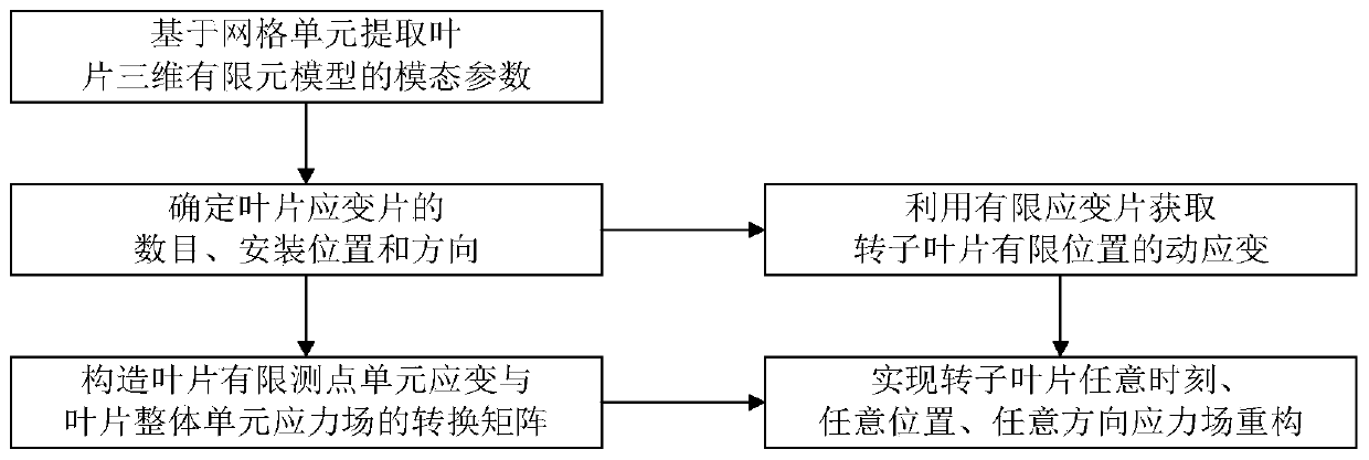
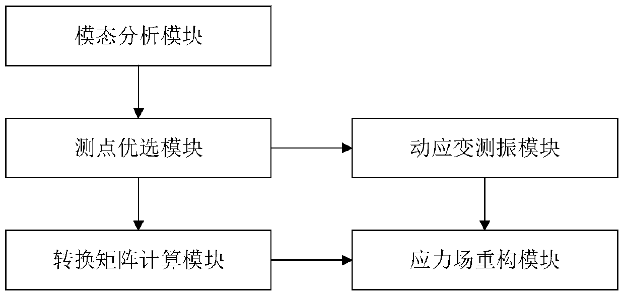
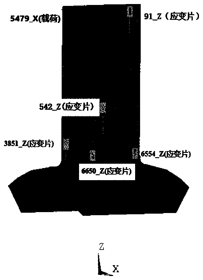
[0042] The following will refer to the attached figure 1 A specific embodiment of the present invention is described in more detail to FIG. 6( d ). Although specific embodiments of the invention are shown in the drawings, it should be understood that the invention may be embodied in various forms and is not limited to the embodiments set forth herein. Rather, these embodiments are provided for more thorough understanding of the present invention and to fully convey the scope of the present invention to those skilled in the art.

[0043] It should be noted that certain terms are used in the specification and claims to refer to specific components. Those skilled in the art should understand that they may use different terms to refer to the same component. The specification and claims do not use differences in nouns as a way of distinguishing components, but use differences in functions of components as a criterion for distinguishing. "Includes" or "comprises" mentioned throug...


PUM


Abstract

The invention discloses a rotor blade dynamic stress reconstruction method and system, and the method comprises the following steps: building a three-dimensional finite element model of a to-be-measured rotor blade, and extracting modal parameters of the three-dimensional finite element model based on a grid unit; determining the number, installation positions and directions of a plurality of strain gauges arranged on the rotor blade; respectively constructing a conversion matrix of strain gauge measuring point unit dynamic strain and blade integral unit stress field and a conversion matrix ofstrain gauge measuring point unit dynamic strain and blade integral unit equivalent stress field; measuring the dynamic strain of the corresponding position unit of the rotor blade based on the strain gauges; and obtaining the dynamic stress and equivalent stress of the rotor blade at any time, at any position and in any direction based on the conversion matrix according to the measured dynamic strain.

Description

technical field [0001] The invention belongs to the technical field of non-contact vibration testing of rotor blades of rotary machines, in particular to a dynamic stress reconstruction method and system for rotor blades. Background technique [0002] The blade is an important part of the aero-engine, and the integrity of the high-speed rotating blade directly affects the safe operation of the overall structure of the aero-engine. When an aero-engine is working, the blades will be subjected to harsh working conditions such as high temperature, high pressure, and high speed, and the blades are prone to vibration fatigue failure during service. Vibration-induced high cycle fatigue is one of the main failure modes of aeroengine blades. During the service of aero-engines, the high-cycle fatigue of blades is mainly caused by the vibration stress (referred to as "dynamic stress") caused by various aerodynamic loads and mechanical loads. The stress amplitude is lower than that of ...

Claims


Application Information

Patent Timeline
IPC IPC(8): G06F30/23G06F30/15G06T17/20G06F119/02G06F119/04G06F119/14
CPCG06F30/23G06F30/15G06T17/20G06F2119/02G06F2119/04G06F2119/14
Inventor 乔百杰朱昱达符顺国杨志勃陈雪峰
Owner XI AN JIAOTONG UNIV
Why Eureka
Try Eureka