Photoelectric composite cable
A technology for optoelectronic composite cables and cable assemblies, applied in the field of optical fiber cables and cables, can solve the problems of lack of optical fiber signal transmission, inconvenient operation of underwater equipment, inability to meet use requirements, etc., to achieve convenient use, convenient and fast maintenance, and saving construction The effect of time and cost
- Summary
- Abstract
- Description
- Claims
- Application Information
AI Technical Summary
Problems solved by technology
Method used
Image

Examples
Embodiment 1
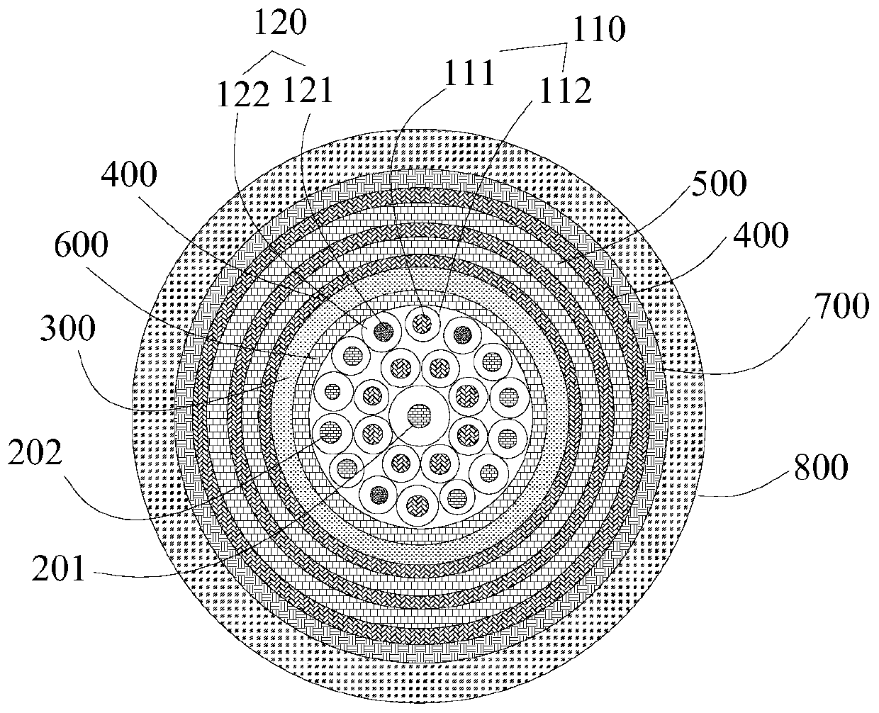
[0063] Such as figure 1 As shown, the photoelectric composite cable of this embodiment includes a cable core, a filling component, an inner sheath 300, a first braiding layer 400, a first wrapping layer 500, a second wrapping layer 600, a second braiding layer 700 and an outer Sheath 800.
[0064] The cable core includes a cable assembly and an optical fiber assembly, and the cable assembly and the optical fiber assembly are twisted to form a cable core;
[0065] Wherein, the cable assembly includes 10 wires 110, and the wire 110 includes a conductor 111 and an insulating layer 112 coated on the outside of the conductor 111; the conductor 111 is a silver-plated copper wire; the insulating layer 112 is an HDPE layer,
[0066] The optical fiber assembly includes three optical fiber units 120, the optical fiber unit 120 includes an optical fiber 121 and a stainless steel protective tube 122 coated on the outside of the optical fiber;
[0067] The filling components are filled i...
Embodiment 2
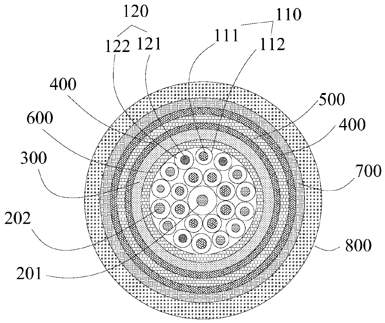
[0078] Such as figure 2 As shown, the photoelectric composite cable of this embodiment includes a cable core, a filling component, an inner sheath 300, a first braiding layer 400, a first wrapping layer 500, a second wrapping layer 600, a second braiding layer 700 and an outer Sheath 800.
[0079] The cable core includes a cable assembly and an optical fiber assembly, and the cable assembly and the optical fiber assembly are twisted to form a cable core;
[0080] Wherein, the cable assembly includes 10 wires 110, and the wire 110 includes a conductor 111 and an insulating layer 112 coated on the outside of the conductor 111; the conductor 111 is a silver-plated copper wire; the insulating layer 112 is an HDPE layer,
[0081] The optical fiber assembly includes three optical fiber units 120, and the optical fiber unit 120 includes an optical fiber 121 and a stainless steel protective tube 122 coated on the outside of the optical fiber;
[0082] The filling components are fil...
Embodiment 3
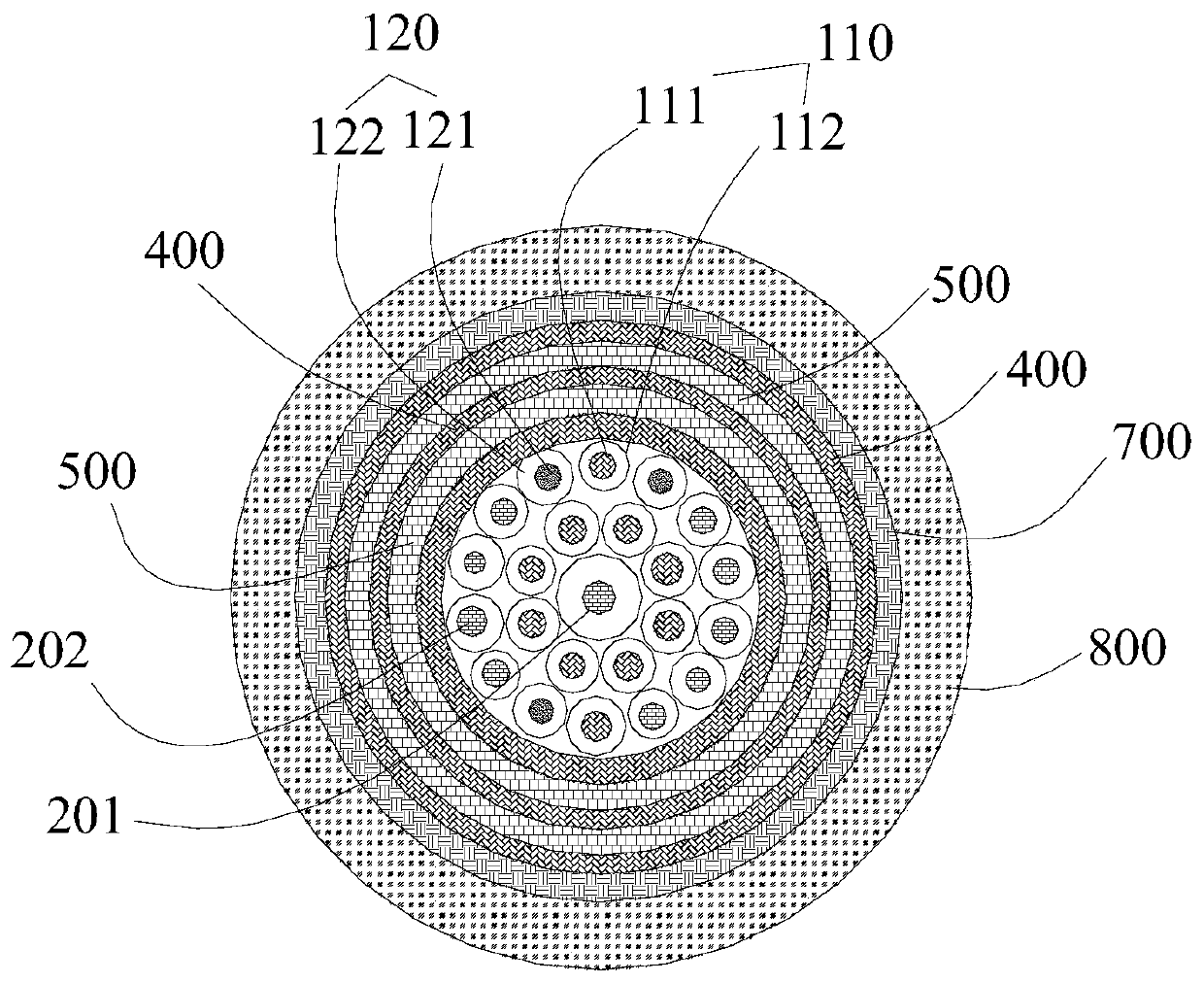
[0093] Such as image 3 As shown, the photoelectric composite cable of this embodiment includes a cable core, a filling component, a first braided layer 400 , a first wrapping layer 500 , a second braided layer 700 and an outer sheath 800 .
[0094] The cable core includes a cable assembly and an optical fiber assembly, and the cable assembly and the optical fiber assembly are twisted to form a cable core;
[0095] Wherein, the cable assembly includes 10 wires 110, and the wire 110 includes a conductor 111 and an insulating layer 112 coated on the outside of the conductor 111; the conductor 111 is a silver-plated copper wire; the insulating layer 112 is an HDPE layer,
[0096] The optical fiber assembly includes three optical fiber units 120, the optical fiber unit 120 includes an optical fiber 121 and a stainless steel protective tube 122 coated on the outside of the optical fiber;
[0097] The filling components are filled in gaps between the wires 110 and the wires 110 , bet...
PUM
 Abstract
Description
Claims
Application Information
 - R&D
- Intellectual Property
- Life Sciences
- Materials
- Tech Scout
- Unparalleled Data Quality
- Higher Quality Content
- 60% Fewer Hallucinations
Browse by: Latest US Patents, China's latest patents, Technical Efficacy Thesaurus, Application Domain, Technology Topic, Popular Technical Reports.
© 2025 PatSnap. All rights reserved.Legal|Privacy policy|Modern Slavery Act Transparency Statement|Sitemap|About US| Contact US: help@patsnap.com