Motor stator winding, motor stator and motor

A motor stator and winding technology, which is applied in the field of motor stator windings, motor stators and motors, can solve the problems of complex arrangement, complex manufacturing process, and low processing efficiency, so as to reduce the complexity of the manufacturing process, reduce production costs, and improve The effect of processing efficiency

Pending Publication Date: 2020-08-21
BORGWARNER POWERDRIVE SYST (TIANJIN) CO CHINA
View PDF0 Cites 4 Cited by
  • Summary
  • Abstract
  • Description
  • Claims
  • Application Information

AI Technical Summary

Problems solved by technology

[0002] The stator winding includes a plurality of hairpin coils, and the multiple hairpin coils are inserted into the slots of the stator core according to a certain arrangement to form the single-phase winding or multi-phase winding of the required motor. The hairpin coils used in the prior art There are many kinds of stator windings, and the arrangement method is complicated, and a large number of bus bars and bus bars are needed to connect the branches and neutral points of each phase winding; in the prior art, more than 90% of the stator windings have the number of slots per pole and each phase Both are greater than or equal to 2, but if the phases of the stator winding are connected in series, the twisting direction of the welding end in the same layer of slots or the pitch of the twisting slots will be inconsistent, the manufacturing process is complicated, the forming is difficult, the production cost is high, and the processing efficiency is low.

Method used


Image

  • Motor stator winding, motor stator and motor
  • Motor stator winding, motor stator and motor
  • Motor stator winding, motor stator and motor

Examples


Embodiment 1

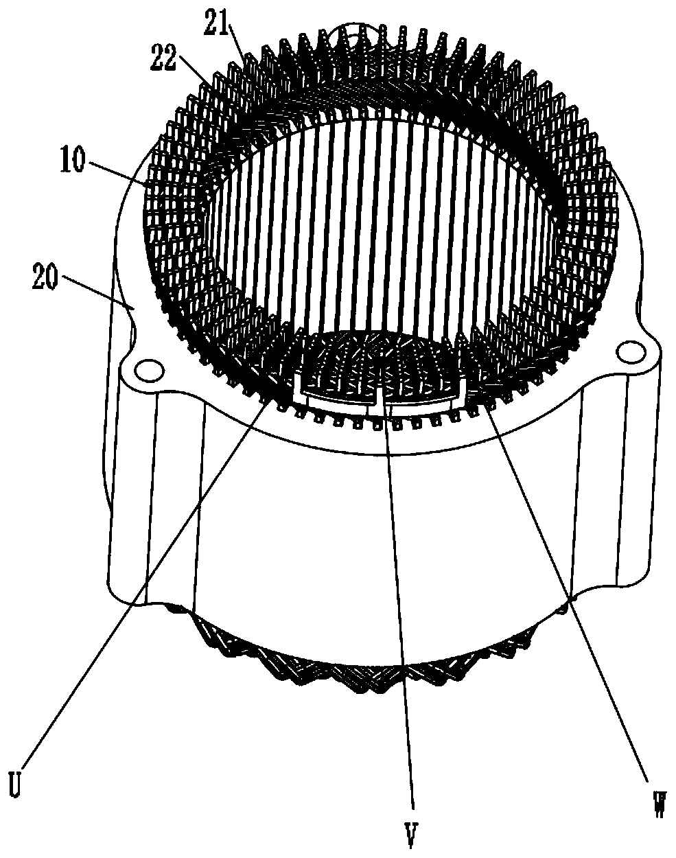
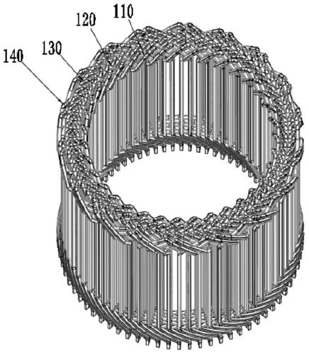
[0105] Such as Figure 1-4 As shown, the stator winding 10 includes a coil group three 110 , at least one coil group one 120 , at least one coil group two 130 , and a coil group four 140 , which are nested sequentially from the inside to the outside;

[0106] Such as Figure 2-4 , 9, and 10, the coil group three 110 is located on the first radially inner layer of the stator core 20, and may also be located on the first radially outer layer of the stator core 20. In this embodiment, the coil group three 110 is located on the stator iron core 20. The first layer radially inside the core 20, the coil group one 120 is located on the second and third layers radially inside the stator core 20, the coil group two 130 is located on the fourth layer and the fifth layer radially inside the stator core 20, the coil group Four 140 are located on the sixth radial layer of the stator core 20;

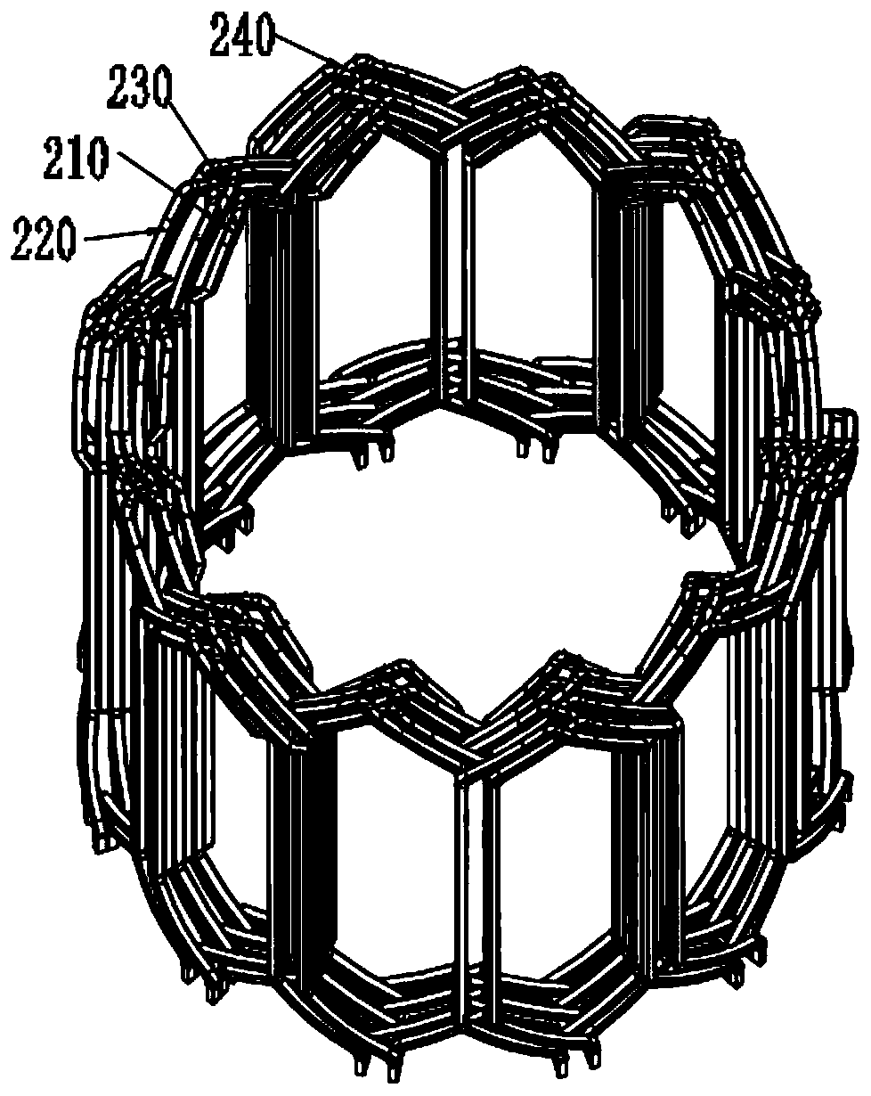
[0107] Figure 5 , 9 As shown in , 10, the coil group 3 110 includes a plurality of conductor...

Embodiment 2

[0112] The stator winding 10 includes coil group three 110, at least one coil group one 120, at least one coil group two 130, and coil group four 140, which are sequentially nested from inside to outside;

[0113] Such as Figure 11-12 , 19, and 20, the coil group three 110 is located on the first radially inner layer of the stator core 20, and may also be located on the first radially outer layer of the stator core 20. In this embodiment, the coil group three 110 is located on the stator iron core The first layer radially inside the core 20, the coil group one 120 is located on the second and third layers radially inside the stator core 20, the coil group two 130 is located on the fourth layer and the fifth layer radially inside the stator core 20, the coil group Four 140 are located on the sixth radial layer of the stator core 20;

[0114] Figure 5 , 19 , 20, the coil group three 110 includes a plurality of conductors three 210, including 36 conductors three 210 in this ...

Embodiment 3

[0125] The stator winding 10 includes coil group three 110, at least one coil group one 120, at least one coil group two 130, and coil group four 140, which are sequentially nested from inside to outside;

[0126] Such as Figure 21-23 As shown, the coil group three 110 is located at the first radially inner layer of the stator core 20, and may also be located at the first radially outer layer of the stator core 20. In this embodiment, the coil group three 110 is located at the radially inner layer of the stator core 20. In the inner first layer, the coil set 120 is located on the second and third layers radially inside the stator core 20, the coil set 2 130 is located on the fourth and fifth layers radially of the stator core 20, and the coil set 4 140 is located on the stator core 20. The iron core 20 is radial to the sixth layer;

[0127] Figure 5 and 23 As shown, the coil group 3 110 includes a plurality of conductors 3 210. In this embodiment, 36 conductors 3 210 are ...


PUM


Abstract

The invention provides a motor stator winding, which comprises at least one coil group I arranged on two radially adjacent layers of a stator core; at least one coil group II arranged on two adjacentlayers of the stator core in the radial direction; a coil group III arranged on the first layer of the radial inner side or the first layer of the radial outer side of the stator core; and a coil group IV arranged on the first layer, opposite to the radial direction, of the coil group III in the stator core. The lap winding rotation direction of the coil group I is opposite to that of the coil group II. According to the invention, conductors in fewer types are used arrangement mode is simple, a bus strip and a bus bar can be canceled, so that the twisting direction and the twisting groove pitch of the welding end part extending towards the inside of the same layer in the stator core groove are consistent, the lead end and the neutral point between the windings of each phase are arranged atany layer of any groove in the same radial direction, the complexity of the manufacturing process is reduced, the production cost is reduced, and the processing efficiency is improved.

Description

technical field [0001] The invention belongs to the technical field of motors, and in particular relates to a motor stator winding, a motor stator and a motor. Background technique [0002] The stator winding includes a plurality of hairpin coils, and the multiple hairpin coils are inserted into the slots of the stator core according to a certain arrangement to form the single-phase winding or multi-phase winding of the required motor. The hairpin coils used in the prior art There are many kinds of stator windings, and the arrangement method is complicated, and a large number of bus bars and bus bars are needed to connect the branches and neutral points of each phase winding; in the prior art, more than 90% of the stator windings have the number of slots per pole and each phase Both are greater than or equal to 2, but if the phases of the stator winding are connected in series, the twisting direction of the welding end in the same layer of slots or the pitch of the twisting ...

Claims


Application Information

Patent Timeline
Patent Type & Authority Applications(China)
IPC IPC(8): H02K3/04H02K1/16H02K3/12H02K3/28
CPCH02K1/165H02K3/04H02K3/12H02K3/28H02K2213/03
Inventor 刘延海柏荣键
Owner BORGWARNER POWERDRIVE SYST (TIANJIN) CO CHINA
Why Eureka
Try Eureka