Turbomachine inner housing

A technology for turbines and inner casings, applied in turbines, mechanical equipment, engine components, etc., can solve the problems of complex manufacturing, complex and expensive manufacturing of the center hole of the sealing surface and the fixing part, and achieve the effect of structural reinforcement.

Pending Publication Date: 2020-08-21
SIEMWNS ENERGY GLOBAL GMBH & CO KG
View PDF39 Cites 0 Cited by
  • Summary
  • Abstract
  • Description
  • Claims
  • Application Information

AI Technical Summary

Problems solved by technology

In addition to the complex manufacture of the annular return-stage flow channel, the manufacture of the sealing surfaces and the required large number of central holes and fixing parts is also very complex and expensive

Method used


Image

  • Turbomachine inner housing

Examples


Embodiment Construction

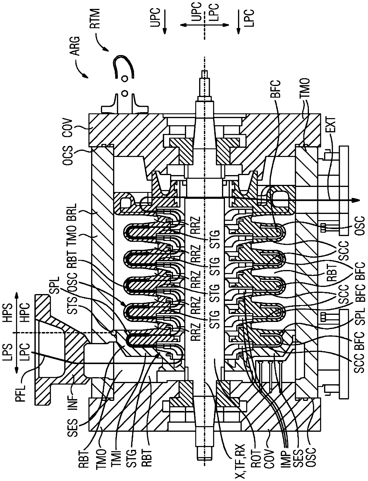
[0022] figure 1 A plant ARG or a radial turbine RTM with a turbine inner casing TMI according to the invention is shown. The inner turbine housing TMI is surrounded by an outer turbine housing TMO, through which the process gas PFL flows from the inflow IMF to the outflow EXT. In a particular embodiment of a radial turbo compressor, the process fluid PFL is subjected to a higher pressure while flowing through the turbine inner casing TMI by means of the impellers IMP, which rotate about the longitudinal axis X or the rotor axis RX Components of the rotor ROT. Here, the turbine inner casing TMI is a static, in particular aerodynamically active structural element, and the rotor ROT with the impeller IMP introduces technical work into the process fluid PFL from an external drive, not shown in detail. For the purpose of coupling the drive, the left-hand and right-hand shaft ends of the rotor are led axially out of the outer housing TMO at through-bores. By means of a shaft seal...


PUM


Abstract

The invention relates to a turbomachine inner housing (TMI) for a radial turbomachine (RTM), wherein the turbomachine inner housing (TMI) comprises a partial joint (TF) along a longitudinal axis (X),in particular a rotor longitudinal axis (RX), such that the turbomachine inner housing (TMI) can be divided into a lower part (LPC) and an upper part (UPC), wherein the turbomachine inner housing (TMI) is designed for a radial turbomachine (RTM) comprising at least two stages (STG), the turbomachine inner housing (TMI) comprises a return stage (BFC) in each case between two stages (STG), and the lower part (LPC) and / or the upper part (UPC) is designed in one piece so as to span at least two stages (STG) at least in sections. In order to improve a turbomachine inner housing of this kind, the lower part and / or the upper part is designed in one piece so as span at least two stages at least in sections.

Description

technical field [0001] The invention relates to an inner turbine casing for a radial turbine, wherein the inner turbine casing has a joint along the longitudinal axis, in particular along the longitudinal axis of the rotor, so that the inner turbine casing can be divided into lower parts and the upper part, wherein the turbine inner casing is designed for a radial turbine comprising at least two stages, wherein the turbine inner casing has a return stage respectively between the two stages, wherein the lower part and / or the upper part are at least Partially integrally formed across at least two stages. Background technique [0002] Radial turbines of the above-mentioned type having a turbine inner casing of this type are already known from publications WO2016026825-A1, WO2010034602-Al, WO2007137959-Al and EP1860326-A1. [0003] The inner casing of the turbine or the inner casing of the turbine, in particular the inner casing of a radial turbine, is always surrounded by the ...

Claims


Application Information

Patent Timeline
Patent Type & Authority Applications(China)
IPC IPC(8): F04D1/06F04D17/12F04D29/42
CPCF04D1/063F04D17/125F04D29/4206F04D29/426F01D25/265F05D2300/603B33Y80/00B22F5/009F05D2230/31F01D25/24Y02P10/25B22F10/18B22F10/25B22F10/28B22F10/12B22F10/14B33Y10/00
Inventor D·纳斯S·内加蒂-拉德K·施克曼
Owner SIEMWNS ENERGY GLOBAL GMBH & CO KG
Why Eureka
Try Eureka