Electrical machine for submerged application and energy conversion system

An energy conversion, mechanical system technology, applied in traditional hydroelectric energy, hydroelectric power, components of pumping devices for elastic fluids, etc., can solve problems such as system efficiency reduction, and achieve the effect of ensuring mechanical rigidity

Inactive Publication Date: 2013-03-20
SMART MOTOR AS
View PDF20 Cites 0 Cited by
  • Summary
  • Abstract
  • Description
  • Claims
  • Application Information

AI Technical Summary

Problems solved by technology

[0047] (c) Reduced system efficiency due to:

Method used


Image

  • Electrical machine for submerged application and energy conversion system
  • Electrical machine for submerged application and energy conversion system
  • Electrical machine for submerged application and energy conversion system

Examples


Embodiment Construction

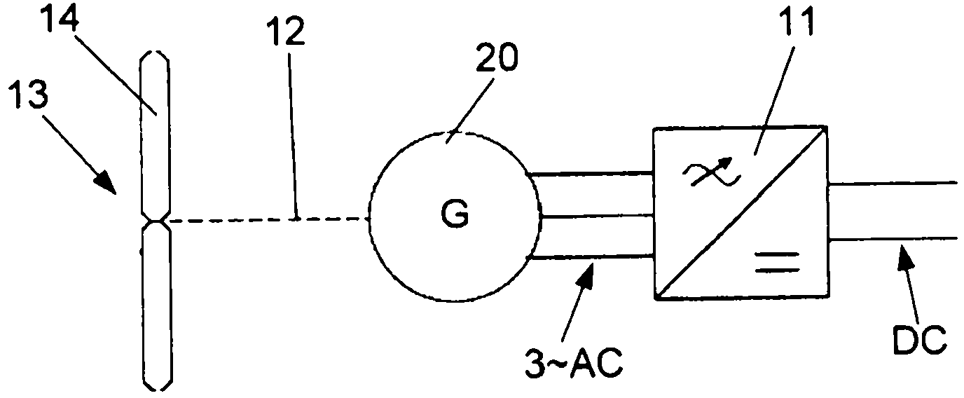
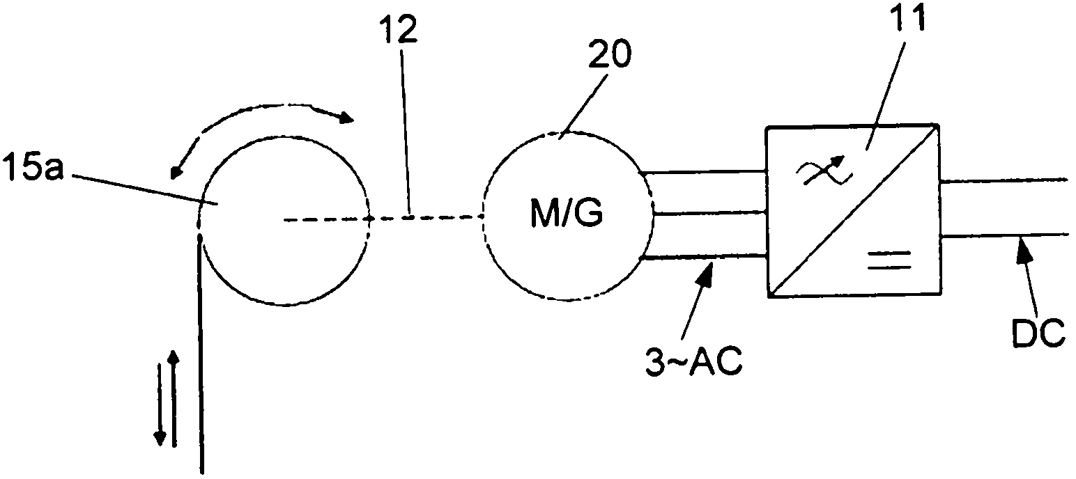
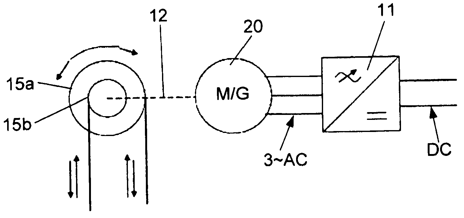
[0091] See now Figure 1A -C, which shows the topology and load form of the energy conversion system proposed by the present invention. Figure 1A Shows a one-way movement with a constant load, Figure 1B Shows a two-way (reciprocating) movement with a main power component, Figure 1C Shows a two-way (reciprocating) movement with two main power components.

[0092] The energy conversion system according to the present invention includes as main components an AC / DC converter 11, a motor 20 (motor "M" or generator "G" according to the operation mode), and a mechanical connector 12 (shaft) connected to the mechanical system 13 Or directly combine). The mechanical system 13 may be the main power component itself, such as the turbine 14, such as Figure 1A Shown in, or is a system of one or more pulleys 15a-b for converting linear motion into rotational motion. There can be a pulley 15a, such as Figure 1B Shown in, or two and more pulleys 15a-b, such as Figure 1C Shown in.

[0093] See ...


PUM


Abstract

The invention relates to an electrical machine for submerged applications and an energy conversion system for conversion of mechanical energy of unidirectional or reciprocating linear or rotational motion into electric energy and vice versa. The electric energy may be in the form of DC or AC current and voltage. The system is totally submerged in pure or salt water. The enabling element of the invention is multi-pole permanent magnet synchronous machine with separately encapsulated stator and rotor, integrated with mechanical system and power electronics.

Description

Technical field [0001] The invention relates to a motor for underwater applications according to the preamble of claim 1. [0002] The present invention also relates to an energy conversion system according to the preamble of claim 15 for converting mechanical energy of unidirectional or reciprocating linear or rotational motion into electrical energy and vice versa. The electrical energy may be in the form of DC or AC current and voltage. The system and motor are particularly relevant for underwater applications, ie immersion in pure water or salt water. Background technique [0003] The underwater energy conversion system can be used in wave, tidal and hydraulic energy conversion plants, auxiliary subsea generators, underwater blade pitch systems, subsea winches, propulsion systems, thrusters, in-tube generators, etc. These applications are characterized by different types of main movements. [0004] Based on the differences in motion and the existing technical solutions, the fo...

Claims


Application Information

Patent Timeline
Patent Type & Authority Applications(China)
IPC IPC(8): H02K5/132F03B13/10F04D13/08H02K9/00H02K21/00
CPCF04D29/026H02K7/1807H02K11/0068Y02E10/38H02K5/132F04D13/08H02K5/1285F03B13/18H02K7/1004H02K1/185H02K7/1016Y02E10/22F03B13/10F05D2300/43F05D2300/603H02K11/30Y02E10/20Y02E10/30
Inventor S·厄夫雷伯S·O·斯托尔内斯A·马特维夫J·霍伊兰德
Owner SMART MOTOR AS
Why Eureka
Try Eureka